For many applications and ECUs in the automotive environment, the voltage provided by the battery and the generator will be insufficient, and it must first be converted to the correct voltage level. Generally, DC / DC switching voltage regulators and linear regulators are used to achieve this goal. This article will focus on the discussion of switching regulators because the linear scheme cannot produce an output voltage higher than the input voltage.
The most commonly used topology is a buck converter (Figure 1). Only a single inductor and a set of diodes and switches are needed to achieve one of the simplest and most cost-effective options in a switched DC / DC solution. However, the only drawback is that this method can only produce an output voltage that is lower than the input voltage. If the output voltage needs to be higher than the input voltage, a "reverse" topology or boost converter can be used (Figure 2). The components required for this topology are similar, but can produce an output voltage that is higher than the input voltage.
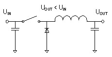
Figure 1: Basic buck converter
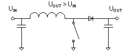
Figure 2: Basic boost converter
Since the fluctuation of the automotive grid voltage is quite large (it can be as low as 3.5V at startup and can be as high as 45V during the clamp load dump), so in some ECU applications, the input and output voltages must cross Situation. During the start-up process (starting the engine), sudden disability is not allowed, especially for power system applications or certain navigation and infotainment systems. This problem can be solved by using a flyback converter or SEPIC topology, but the transformer type The extra cost and space of the inductor is relatively large, making it less attractive to customers.
Even if the input voltage crosses the output voltage value, the buck-boost topology can still provide a stable output voltage, and it has a simple design using only a single coil. In the same topology, it combines a buck and a boost converter. The seamless transition between the two different modes can produce a stable and uninterrupted output voltage under all input voltage conditions.
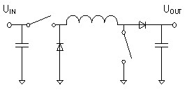
Figure 3: Asynchronous buck-boost converter
Two different topologies are combined here, so compared to a simple buck or boost method using a set of switches and diodes, an asynchronous buck-boost converter requires two sets of switches and diodes (Figure 3). In order to improve the overall efficiency, the diode can be replaced with a switch. The current topology and inductance look similar to a complete H-bridge (Figure 4).
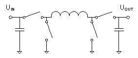
Figure 4 Switch replaces diode
The general functions of these devices can be subdivided into three modes of operation:
1. Buck mode when input voltage is higher than output voltage
2. Boost mode with input voltage lower than output voltage
3. The transfer of input voltage in the output voltage range
Buck mode operation
In operation in buck mode, the input voltage must be higher than the output voltage, similar in function to the basic buck topology. In the buck mode, the converter's boost switches (B1 and B2) will not switch, and the B1 switch must be off, which allows current to flow from the inductor to the output capacitor. The B2 switch must be turned on to avoid short-circuiting the output to ground (GND).
When switching to "on time", the A1 switch is turned off to charge the inductor (Figure 5). During this period, current flows from the input through the A1 switch, coil, and B1 switch, and into the output capacitor.
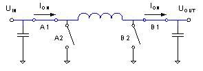
Figure 5: Current flow of the buck converter during the conduction phase
In the second phase of the cycle (off time), the A1 switch will turn on and the A2 switch will turn off (Figure 6). The magnetizing coil will force the current from GND to flow through the A2 switch, coil, B1 switch, and then into the output capacitor (also known as the flywheel).
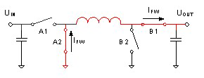
Figure 6: Current flow of the buck converter in the flywheel stage
In the asynchronous topology, the A2 switch is replaced by a diode as a passive flywheel component. This reduces the number of drivers and field-effect transistors (FETs) used, but it also reduces the efficiency of the converter. The switching duty cycle in this operation is based on the input-to-output voltage ratio shown in Equation 1.
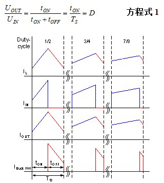
Figure 7: Current waveform during buck switching
An Indoor Access Point is a device for wireless local area networks (WLAN) that provides wireless network coverage and connectivity. It can connect to a wired network and transmit data via a wireless signal, allowing users to connect to the network wirelessly within coverage.
Indoor access points come in a variety of different types and specifications to suit different scenarios and needs. Here are some common types of indoor access points:
1. Single Band Access Point: A single band access point operates in the 2.4GHz band and typically provides a maximum transfer rate of 300Mbps. This type of access point is suitable for small office or home networks because the 2.4GHz band has better penetration and coverage, but a relatively low transfer rate.
2. Dual Band Access Point: The dual band access point supports both 2.4GHz and 5GHz bands, providing higher transmission rates and better performance. The 5GHz band has more interference free channels than the 2.4GHz band, which can provide faster speeds and more stable connections. Dual-frequency access points are suitable for medium sized offices, malls or hotels.
3. Lightweight Access Point: A lightweight access point is a wireless network device that needs to be used with a network controller. Lightweight access points do not have independent management functions themselves, but are centrally managed and configured via a network controller. This type of access point is suitable for large enterprises or organizations to enable centralized management and monitoring of the entire network.
4. Standalone Access Point: A standalone access point is a standalone device that has its own management and configuration functions and does not require additional network controllers. This type of access point is suitable for small businesses or individual users and can provide a simple and easy-to-use wireless networking solution.
5. Scalable Access Point: A scalable access point is a device that can scale on demand, increasing or decreasing the number of access points based on network demand. This type of access point is suitable for places that require flexible scaling, such as large office buildings, schools, or hospitals.
In addition to the types listed above, there are some special purpose indoor access points, such as:
1. Wall-mounted Access Point: A wall-mounted access point can be plugged directly into a Wall power outlet without the need for an additional power cord. This type of access point is suitable for home networks or small offices and can provide easy installation and use.
2. Integrated Antenna Access Point: The antenna of the antenna access point is integrated into the device, and no additional antenna installation is required. This type of access point is suitable for sites that require simple installation and a nice look.
3. Multiple Antenna Access Point: Multiple antenna access points can achieve better signal coverage and performance through multiple antennas. This type of access point is suitable for large venues or high-density user environments, such as conference rooms, stadiums or airports.
To sum up, there are many different types and specifications of indoor access points, which can be selected according to different scenarios and needs. Whether it's a small office, home network or a large enterprise, you can achieve convenient wireless network coverage and connectivity through indoor access points.
Indoor Access Point,Access Point Ceiling,Ceiling Wifi Access Point,Ceiling Mounted Wireless Access Point Poe
Shenzhen MovingComm Technology Co., Ltd. , https://www.movingcommtech.com