Magnetorheological Fluids (Magneto Rheological Fluids) is a new phase change material. It is a magnetic particle suspension composed of a combination of high magnetic permeability, low hysteresis of tiny (micron or even nanometer) soft magnetic particles and non-magnetically permeable liquid. When there is no magnetic field, the suspended particulate iron particles move freely with the liquid; when the magnetic field is applied, the suspended particulate iron particles are attracted to each other to form a string of chain structure from one pole of the magnetic field to the other pole. The rheological liquid changes from Newtonian fluid to plastomer or viscoelastic elastomer with a certain yield shear stress at the moment of milliseconds. When the current in the magnetic field coil is changed to obtain magnetic fields of different strengths, the yield shear stress of the magnetorheological fluid also changes, that is, under the action of a strong magnetic field, the shear resistance is large, and a liquid with high viscosity and low fluidity is exhibited. Characteristics; exhibits low viscosity characteristics under zero magnetic field conditions. The shear yield strength has a stable correspondence with the magnetic field strength (or current magnitude). It is this rheology controllability of magnetorheological fluid that enables it to achieve a continuously variable damping force for active control of vibration.
Magnetorheological fluid belongs to the international research frontier technology and has broad application prospects in the fields of vehicles, machinery, aerospace, shipbuilding and construction. Magnetorheological fluid technology is increasingly used in active vibration and torque transmission applications such as shock absorbers, anti-vibration dampers, suspension systems for Cadillac vehicles, seismic isolation devices for large construction projects, clutches, and flexible clamps. , optical device polishing, etc., even in the medical field, artificial prosthetics also use magnetorheological fluid technology. LORD has developed the current controller RD-3002 for the Rheonetic series of magnetorheological devices. It can work in manual adjustment and external voltage control adjustment, and can form a closed-loop control system with computer or PLC. The RD-3002 requires an external 12 V/2 A power supply with an output current of 0 to 2 A, which is more expensive. A current control system for magnetorheological dampers was designed using Motorola's MC68HC908GP32 MCU as the core. The 16-bit fixed-point general-purpose digital signal processing chip introduced by TEXAS Instruments has developed a precise and controllable current controller. However, these research and development are more complicated and cannot be separated from computer work and costly. It is especially inconvenient when debugging a magnetorheological fluid damper on site.
This paper proposes a simple and tight controllable PWM (Pulse Width Modulation) closed-loop current amplifier with high precision, good linearity, high efficiency, convenient debugging and low cost. It can be used not only for magnetorheological fluid damping devices, but also for Can be used in any solenoid circuit, heater or lighting circuit.
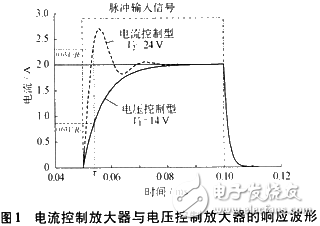
1 DRV series PwM driver structureThe current control method of the electromagnetic coil generally has two types of voltage control and current control. The voltage control method is to adjust the terminal voltage of the coil to control the current through the electromagnetic coil; the current control method is to change the current of the electromagnetic coil under the full voltage. Since the load changes, for example, the coil resistance changes due to temperature, only regulating the voltage causes a current error. The strength of the magnetic field is proportional to the magnitude of the current, and the damping cylinder requires a fast response. Assuming a load resistance of 5 Ω, the load requires 1 A at some point. For voltage-controlled amplifiers, the load voltage is controlled to 5 V. For current-controlled amplifiers, the load voltage may be 12 V or higher at this point. At the instant of a signal pulse input, the load current will exceed 1 A and then return to 1 A. The current rise waveform is shown in Figure 1. At the same coil current, the current rise time of the current-controlled amplifier is significantly less than the rise time of the voltage-controlled amplifier. This is because the current amplifier can pass through the coil faster at full voltage, and the current amplifier is easy to achieve current compensation. After the signal pulse is cancelled, the waveforms of the two types of amplifiers substantially coincide, which is due to the exponential decay of the coil discharge.
Conventional linear output power supplies provide a continuous voltage to the electronic system; however, this type of power supply operates in the linear region of the semiconductor device and will cause the greatest power loss. There is an important conclusion in the sampling control theory: narrow impulses with equal impulses and different shapes are added to the links with inertia, and the effects are basically the same. The SPWM (Sinusoidal PWM) method is based on this conclusion. The PWM waveform that is equivalent to the sine wave with the pulse width is sinusoidal, that is, the SPWM waveform is used to control the on/off of the switching device in the inverter circuit, so that the pulse is output. The area of ​​the voltage is equal to the area of ​​the desired output sine wave in the corresponding interval. By changing the frequency and amplitude of the modulated wave, the frequency and amplitude of the output voltage of the circuit can be adjusted or the output current of the circuit can be adjusted. The PWM uses a digital output to drive the analog circuit for maximum energy transfer efficiency and power savings with higher reliability. The regulated PWM allows for more precise control of the load current.
The US company TxAs Instruments has designed and produced a series of PWM integrated chips for driving relays, solenoids, electric actuators, heaters and lighting. The DRV103 is one of them. Its size is 5 mm × 6 mm, adjustable delay time, Adjustable oscillation frequency, adjustable duty cycle and low price make it suitable for a wide range of applications. The DRV103 has two modes of operation: switch drive and continuous drive. The DRV103 can be set to the original closed mode, in which it can automatically switch to the power saving mode. Figure 2 shows a simplified block diagram and pins for the DRV103.
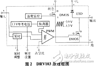
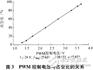
Pin 1 is connected to a comparator and a current source (=2.75ref and Iref=1.3V/Rfreq). Pin 1 can be grounded through a resistor RPWM or connected to an analog voltage to adjust the duty cycle. This analog voltage range is between 1.3 V and 3.9 V. When the PWM frequency is set at 25 kHz, RPWM is taken as 75 kΩ, the duty ratio is 10%; when RPWM is taken as 200 kΩ, the duty ratio is 90%. When the analog voltage or D/A converter is used, the analog voltage or D/A converter must be able to provide sinking capability (=2.75, Iref and Iref=1.3 V/Rfreq).
Pin 2 is the initial time to set the DRV 103 from DC (100% duty cycle) to PWM mode after power-on, that is, delay adjustment. It is internally connected to a 3μA current source and a 2.6V threshold comparator. When the voltage on pin 2 is lower than 2.6 V, DRV103 is the 100% duty cycle output _. When this foot is left floating, the delay time is 18μs. This is caused by the internal odd capacitor. If less time is needed, it can be connected to +5 V, and the delay time can be reduced to 1 μs. When pin 2 is connected to a 10 μF capacitor, the delay time can be 11 s. The PWM frequency is determined by the grounding resistance of pin 3. The DRV103 internal oscillator has a frequency range of 500 Hz to 100 kHz. However, at 500 Hz, the external resistor value will reach 10 MΩ. Pin 2 will be a high impedance input node and will be very sensitive to electrical noise signals. The external resistor values ​​are 523 kΩ, 205 kΩ, and 1100 kΩ when the PWM frequency is 10 kHz, 2 5 kHz, and 50 kHz.
The DRV103 outputs a 3 A drive current (pin 5) through a power DMOS tube, enough to drive a small to medium solenoid. Its on-resistance is 0.5 Q, ensuring low power consumption. The gate drive with the highest rise rate limit can reduce RFI/EFI radiated noise. When driving an inductive load, the clamped diode ESD inside the DRV103 cannot replace the external discharge diode. Pin 7 is the fault indication output. When overcurrent or overheating, a sink current channel is provided to drive the light-emitting diodes, and the maximum sink current is limited to 10 mA. Pin 8 is a TTL level compatible input port. Above 1.7 V, DRV103 provides a PWM output; below 1.7 V, DRV103 has no PWM output. Pin 8 cannot be “connected to the power supply, otherwise it will damage DRV103. Pin 6 is the power supply and its range is +8 v to +32 V, which must be greater than the load supply voltage.
The electrical characteristics of the DRV103 (typical values) are as follows:
Output current (pin 5) 1.5 A, SO-8 package (U);
Output current (pin 5) 3 A, power PADTM package (H);
Maximum current limit (pin 5) 3.5 A, above this value, return to zero;
On-resistance 0.4 Ω;
The output voltage is +0.4 V, I0=1 A;
Digital control input (pin 8) +2.2 V to +5.5 V (TTL level), high level enabled;
Constant DC output vs. PWM delay (pin 2) 110 ms, depending on external capacitance;
Occupancy ratio adjustment (foot 1) 10% to 90%;
Duty cycle accuracy ±2%, 25 kHz, 50% duty cycle;
Nonlinear l%FSR;
Dynamic response: output voltage rise time 0.2μs, output voltage fall time 0.2μs, oscillation frequency range 0.5 kHz ~ 100 kHz, Rosc = 205 kΩ, f = 25 kHz;
Working temperature -55 ° C ~ +125 ° C;
Temperature protection +160 ° C, recovery at +140 ° C;
Fault output (pin 7) 5 V, 20 kΩ pull-up to +5 V;
Fault output sink current 2 mA;
Power supply range (pin 6) +8 V to +32 V.
Note: The output current is limited by the DRV103 power dissipation. When the output current upper limit is reached, the output current will be set to zero. Constant DC output vs. PWM delay = 1.1 Cn x 106 (CD unit is F). The power PADTMSO-8(H) package has a long-term maximum operating current of 2 A under the heat sink.
Figure 3 shows the relationship between the PWM control voltage and the duty cycle.
The magnetorheological liquid controllable current amplifier circuit developed by DRV103 is shown in Fig. 4.
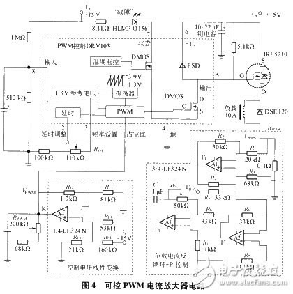
The controllable current amplifier consists of three parts: PWM control DRV103, load current feedback link and duty cycle voltage signal linear transformation. Due to the large current required for a variety of performance experiments in the study of magnetorheological fluids, a first-stage current drive is added to the DRV103 output to maximize the drive current to 40 A. This stage driver uses the HEXFET power MOSFET IRF5210 manufactured by International Rectifier, which has a maximum operating current of 40 A, a reverse voltage of 100 V, and an on-resistance of 0.06 Ω. For larger output currents, the IRF4905 can be used with a maximum operating current of 74 A, a reverse voltage of 55 V, and an on-resistance of 0.02 Ω. The fast recovery epitaxial diode DSE120 provides a fast path for solenoid discharge and protects the MOSFET tube IRF5210. The PWM oscillation frequency is adjustable. When the resistance Rref is adjusted to 205 kΩ, the oscillation frequency is set at 25 kHz. When the resistance Rref is adjusted to 100 kΩ, the oscillation frequency is set at 50 kHz. However, if the oscillation frequency is set at 50 kHz, the duty cycle adjustment will change, no longer the curve shown in Figure 3. The system automatically works (automatically enabled) after power-on, without the need for additional control signals.
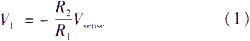
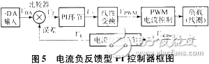
When the temperature changes cause the load resistance value to change, the current is unstable, which affects the magnetorheological liquid damping effect. The magnetorheological liquid controllable current amplifier can be designed as a current feedback control type, as shown in Figure 5. That is, a sampling resistor Rsense is connected in series with the load, the current signal is taken out, a negative feedback amplifier A1 is input, and the voltage V1 is taken out:
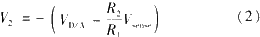
After error comparison amplifier A2, when R4=R5=R6, there is error output voltage V2:
After PI operation, its output V3 is:
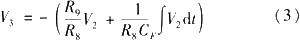
Under a constant D/A input signal, if the load current becomes larger due to temperature, Vsense becomes larger. According to equation (3), V3 will become smaller and the duty ratio will decrease, resulting in a decrease in output current. The offset load current is increased to keep the load current stable. If the current consumption of the sampling resistor is too large and the heat is severe, the current feedback loop can be eliminated.
Considering that many new D/A converters do not have sinking capability, and the output of D/A is usually 0 V to +10 V, if D/A is directly connected to pin 1, a large dead zone will occur. Unless separated in software programming. For ease of use, a linear transformation of the duty cycle input control voltage is required. According to Figure 3, set the PWM regulation equation to:
The output equation of the D/A converter is:

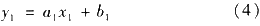
Considering the same output effect, y1=y2, you can find the relationship between the two inputs:
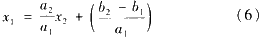
Where: a2/a1 is the reduction and rotation factor in the new coordinate system; (b2-b1)/a1 is the translation factor in the new coordinate system.
In order to achieve this linear transformation, a high-speed single-supply quad op amp LF324N (A4) is used as a voltage input signal conversion adapter. The peripheral resistance parameter [7] is appropriately selected according to the following formula:
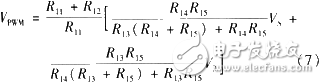
When the D/A output is OV, the output of op amp A4 is 1.3 V; when the D/A output is 10 V, the output of A4 is 3.9 V, just in the duty cycle adjustment range. The 100 pF capacitor is designed to improve the waveform of a large current during fast switching and is connected to the duty cycle adjusting resistor. The 200 kn potentiometer can manually adjust the system output without connecting to a computer or D/A. The switch K must be disconnected for manual adjustment.
The current amplifier is used to drive the electromagnet OP2025 (the internal resistance is 3.5 Ω). The GM04 Gauss meter is used to measure the magnetic field strength of the electromagnet OP2025. The relationship between the D/A output voltage and the output current and magnetic field strength is shown in Fig. 6. The linear coherent error is ±1%. When the D/A output is 10 V, the duty ratio is 100%, the power FET is fully turned on, and the power supply voltage is applied to the load, showing good control effect.
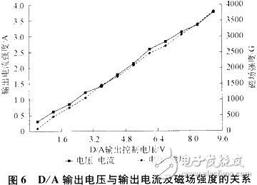
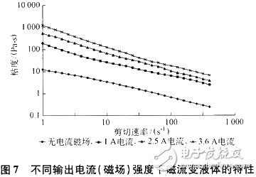
Figure 7 shows the mechanical properties of a self-made magnetorheological fluid measured by a viscometer at different current (magnetic field) intensities. At a current of 3.6 A, the viscosity of the magnetorheological fluid is increased by at least two orders of magnitude compared to when there is no current.
The magnetorheological liquid controllable current amplifier can linearly change the magnetic field strength to achieve variable damping operation. The controllable current amplifier is highly integrated. The PWM chip is constructed. At full voltage, the solenoid can respond quickly to changes in current, ie variable damping cylinders can quickly provide different damping. This feature is especially important when applied to objects moving at high speeds. The controllable current amplifier is small in size and extremely low in cost, and can be used not only for magnetorheological fluids, but also for special requirements in many occasions. The entire system can work independently from the computer, and various parameters are convenient to set and adjust. The current closed-loop compensation temperature drift, the system can work stably for a long time, and the control effect is good. The experimental curves and results give the relationship between the D/A control voltage and the magnetic field strength, showing a good control effect.
LED Par can
LED PAR LIGHT Series
54X3W rgbw; 18x12w RGBW;24x12w RGBW is hot selling in the market. It have waterproof and non-waterproof
Features:
- RGBWA+UV color, 6-in-1 LEDs, excellent color mixing
- quiet working, suitable for quiet applications like theater, studio,etc
-
suitable for events where indoor/outdoor flexibility is needed
- Adjustable PWM (Pulse Width Modulation) to avoid flickering on camera
- Advanced optics provide exceptional color mixing and high efficiency
- Smooth dimming curves for eliminate flicker and choppiness in fades
Our company have 13 years experience of LED Display and Stage Lights , our company mainly produce Indoor Rental LED Display, Outdoor Rental LED Display, Transparent LED Display,Indoor Fixed Indoor LED Display, Outdoor Fixed LED Display, Poster LED Display , Dance LED Display ... In additional, we also produce stage lights, such as beam lights Series, moving head lights Series, LED Par Light Series and son on...
LED Par Light Series,Led Par Can Lights,Par Can,Led Par Stage Light
Guangzhou Chengwen Photoelectric Technology co.,ltd , https://www.cwstagelight.com