Abstract: According to the signal calibration and routine maintenance and debugging requirements of a certain type of TV image transmitter detector, a low-power, frequency-point and power-controllable video transmitter controlled by a single-chip microcomputer with the phase-locked loop technology as the core is developed. (Beacon machine). The design method and system composition of the beacon based on phase-locked loop chip ADF4360 are given, and the software and hardware design scheme of the system is expounded. The test results show that the beacon machine designed by this method has stable and reliable frequency conversion characteristics, and all the indicators have met the requirements. In the actual use process, the operator can conveniently set the required frequency and power points, and the human-machine interface is friendly, which makes the operation more flexible and convenient, and has good cost performance and market prospect.
Keywords: video transmission; signal calibration; phase-locked loop; ADF4360
A certain type of TV image transmitter detector has been successfully developed and put into production. Since the transmitter is completely sealed and reinforced, the detection of its main parameters and indicators can only be indirect, and the most important indicator, its transmit power, can only be received wirelessly. According to the AGC that receives the signal, since the environment has a great influence on the wireless signal, the calibration work in the daily use, maintenance and debugging of the detector is very important. At present, the RF signal instruments produced by Agilent and RS in the United States meet the requirements of use, but they are expensive, bulky, and difficult to carry. Therefore, it is necessary to design a beacon for the model. Replacing expensive imported equipment and reducing equipment costs. The following focuses on the design and implementation of this type of power and frequency point controllable video transmitter (beacon machine).
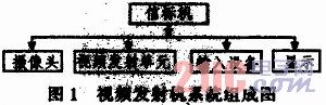
1 The system consists of a beacon as a tool for the calibration detector. It not only requires frequency and power adjustment, but also perfectly simulates the video transmitter of the model to be tested. It also has frequency stabilization, power linearization adjustment and parameter display. Features. According to the above design requirements, the video transmitter uses an analog transmission method to transmit images, and is composed of a single chip microcomputer, a liquid crystal screen, a keyboard, a micro camera, a power supply, and a frequency modulation transmitting circuit. Its system composition is shown in Figure 1.
This article refers to the address: http://
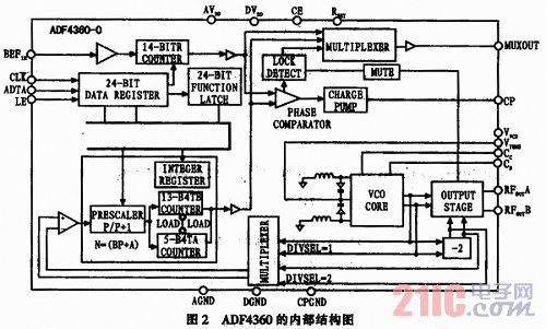
Among them, the frequency synthesis technology in the FM transmission circuit in the video transmission unit is the key to this design. The current mature frequency synthesis technology is the phase-locked loop technology (PLL: Phase Lock Loop). The phase-locked loop technology adopted in this scheme is based on the ADF4360 chip. The ADF4360 chip is a high-performance integer phase-locked frequency synthesizer chip produced by Analog Devices, Inc., which integrates a voltage-controlled oscillator with a digital phase detector, a charge pump, and a programmable reference divider R (14 bit). Programmable A (5 bit) preset, B (13 bit) counter and dual mode front (P/P+1) divider. Its operating frequency range is 2 400 ~ 2 725 MHz, the operating voltage is 3.0 ~ 3.6 V, programmable dual-mode prescaler is 8 / 9, 16 / 17, 32 / 33, the output power programmable range is -13~6 dBm, programmable charge pump current, programmable back-flux pulse width, capable of analog and digital lock detection, hardware and software power-down mode, and simultaneous three-wire transmission. The internal circuit structure of the ADF4360 is shown in Figure 2. Since the chip contains a VCO (Voltage Controlled Oscillator), an external loop filter is required to form a complete phase-locked loop, which is simple in design and low in cost. The ADF4360 chip outputs a suitable frequency division ratio through the control of the single-chip microcomputer, and obtains a stable frequency and power. At the same time, the single-chip microcomputer controls the corresponding value in real time on the LED screen, and also sets the input operation of the keyboard, which is simple and convenient to use.
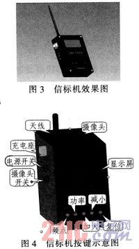
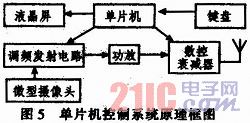
This type of frequency point and power controllable video transmitter (beacon machine) is small in size, low in cost, much smaller than conventional signal sources, and easy to carry. It can be used in a field environment to give a certain type of TV image transmitter detector. Providing a stable and reliable calibration signal source provides great convenience for the actual work. Figure 3 is a rendering of a video transmitter (beacon), and Figure 4 is a diagram of the button of the body.
2 system design and implementation
2.1 Micro Camera The main function of the miniature camera is to capture the image signal and output the video signal in PAL format. After the micro camera completes the acquisition of the image information, the video signal is sent to the FM transmitting circuit for signal modulation, and finally the collected video signal is displayed on the display interface of the monitor.
2.2 Single-chip microcomputer control circuit The function of single-chip microcomputer is mainly divided into two aspects. On one hand, it regularly queries the information of the disk, controls the frequency of the frequency-modulated transmitting circuit, controls the attenuation value of the digitally controlled attenuator, and makes the frequency of the beacon output output. Power signal; on the other hand, the control LCD LED displays the corresponding frequency and power values ​​and other relevant information. The single-chip microcomputer used in this scheme is the main control chip of American ATMEL ATmega 128 single-chip microcomputer. The single-chip microcomputer is based on RISC structure, which has many advantages such as fast, flexible, strong encryption and easy implementation. The data throughput rate is up to 1MIPS/MHz, which is common. 10 times the complexity of the instruction set microprocessor, can reduce the contradiction between system power consumption and processing speed. When the drive sends a variable frequency command, the microcontroller changes the frequency division ratio on the ADF4360 chip after receiving the command, thereby obtaining the desired frequency, and displaying the frequency value on the LED.
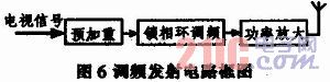
2.3 FM Transmitter Circuit The FM transmitter part is mainly responsible for frequency modulation and transmission of the analog video signal collected by the micro camera. The block diagram of the FM transmitting circuit is shown in Figure 6, including a pre-emphasis circuit, a phase-locked loop frequency modulation circuit, a power amplifying circuit and a transmitting antenna. The phase-locked loop technology is the core of the system. The pre-emphasis circuit first depresses the low-frequency component of the video signal and raises the high-frequency component, and then the video signal controls the VCO to generate the required center frequency together with the error DC signal of the phase-locked loop, and the phase-locked loop divides the output frequency of the VCO. After the frequency, the signal divided by the reference frequency is phase-detected, and the error signal is output, and the error DC signal is formed by the low-pass filter; the modulated signal generated by the video signal to the VCO control is sent to the power amplifier for power amplification to improve The transmit power of the signal increases the distance traveled. The system requires miniaturization and low power consumption of wireless video transmission, and the transmission distance should be as far as possible. Therefore, the FM modulation method is selected when designing the system, because the power, frequency, antenna efficiency and environment are the same. The FM mode will be transmitted farther than other modulation methods (such as AM modulation).
The design of the phase-locked loop adjustment circuit is the core of this solution. It should meet the following requirements:
1) The video signal has a large bandwidth, so it has a relatively large modulation frequency offset;
2) The image signal has higher linearity requirements, otherwise the image distortion and distortion are easy to occur;
3) The circuit is simple, the size and quality must meet the requirements of micro-small.
Considering the above factors, a simple and easy to implement direct frequency modulation method is selected.
The method of directly using the varactor diode for frequency modulation is simple in principle and large in frequency deviation, but the modulator is composed of a common LC self-excited oscillator and a parallel varactor diode. Therefore, there are many factors that cause the oscillation frequency to change. These factors include the nonlinearity of the varactor diode, the variation of the power supply voltage, the change of the load, the change of environmental conditions such as temperature, the aging of the circuit components, and the mechanical vibration. In order to eliminate the above factors causing the instability of the center frequency, in addition to paying attention to the design of the circuit and structure, a phase-locked loop frequency modulation method is selected to stabilize the center frequency. The block diagram of the phase-locked loop FM circuit of the ADF4360 chip is shown in Figure 7.
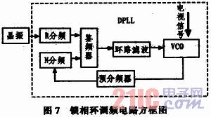
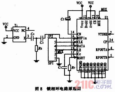
Its external circuitry requires only a loop filter and a reference input, all of which can be configured via control words. Its output frequency range is F0-F6, it is powered by 3.3 V-3.6 V. It has a programmable prescaler, which is convenient for users to change its division ratio. The output power level is adjustable, which is convenient for changing the output power. External communication uses a simple three-wire serial interface and is easy to use. The chip is widely used in wireless handheld devices, test instruments, wireless LANs and CATV devices. The schematic diagram of the phase-locked loop circuit based on ADF4360 is shown in Figure 8.
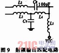
The chip has two outputs: RFoutA and RFoutB, which are in opposite phase. To get a large output power, you need to match the output. There are many ways to match the output. The best way to match the output is to combine RFoutA and RFoutB, as shown in Figure 9. This circuit provides 5 dBm of output power.
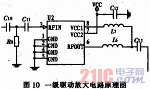
2.4 Power Amplifier Circuit Since the output gain of the voltage controlled oscillator is not large, if the antenna is directly transmitted, the transmission distance will be very close, so the power amplifier circuit must be added to increase the transmission power of the circuit and increase the signal transmission. distance. According to the power requirement, the scheme adopts the first-level drive amplification, and the RF2301 of the RF company is selected. The amplification gain of the chip is 20 dB, the output power of the integrated VCO is -4 dBm, and the power after amplification is 18 dBm (63 mW). The circuit principle is shown in Figure 10.
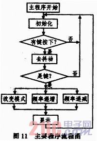
3 system software design The software design of the system mainly includes keyboard scanning subroutine LED display subroutine and phase-locked loop chip control subroutine design. The keyboard scanning subroutine adopts the program scanning mode, and all the programs are designed in assembly language. The phase-locked loop chip control subroutine, the core of which is the implementation of the data processing algorithm. The related program flow chart is shown in Figure 11.
4 Conclusion The video transmitter has been systematically adjusted, and all the indicators have reached the predetermined requirements. At the same time, the system runs stably and reliably, the frequency adjustment is flexible and convenient, simple and practical, especially the use of outdoor work shows the design of the beacon. The portable features have been successfully applied in the daily maintenance of a certain type of image transmitter detector, and have achieved good results.
Optical Fiber Patch Cord,Outdoor Ruggedized Patch Cords,Duplex Armoured Patch Cord,Indoor Patch Cord
ShenZhen JunJin Technology Co.,Ltd , https://www.jjtcl.com