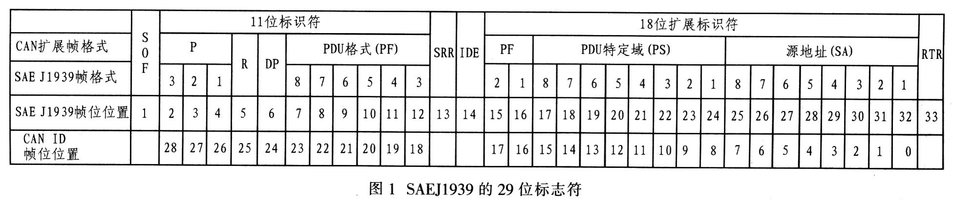
2 SAE J1939 Protocol Overview The SAE J1939 standard is a serial communication and control protocol for vehicle networks based on the CAN bus issued by the Societv of Auto-motive Engineers (SAE). The SAE J1939 protocol is based on the CAN2.0B protocol. Basic, communication speeds up to 250 Kb/s. It stipulates the address configuration, naming, communication mode and message transmission priority of the car's internal ECU, and specifies the ECU communication of each common body inside the car. The SAE J1939 application layer protocol details the parameters of the SAE J1939 network, including data length, data type, resolution, range, and reference labels, and assigns a number (SPN) to each parameter. The information is transmitted by a Protocol Data Unit (PDU), and each PDU is equivalent to one frame of the CAN protocol. SAE J1939 is a transport data protocol, and its functions are divided into two parts: data splitting and reassembly and connection management. The PDU consists of a 29-bit identifier and 0-8 bytes of data, as shown in Figure 1. SAE J1939 provides a complete network definition with a 29-bit identifier (CAN extended frame). In Figure 1, the P bit determines the first 3 bits of the message priority; R is the reserved bit; DP is the data page bit: the PF field identifies 2 PDI formats (PDU1, PDU2); the alternate remote request bit SRR and the identifier extension bit The IDE is not included in the PDU; the PS field is determined by the PF value whether it contains a destination address (DA) or a group extension (GE) for the PDU format PF; the SA is the source address.
This article refers to the address: http://
SAE J1939 uses multiplex technology to provide standardized high-speed network connections based on CAN bus for various sensors, actuators and controllers of automobiles, enabling high-speed data sharing between in-vehicle electronic devices, effectively reducing the number of electronic harnesses Improve the flexibility, reliability, maintainability and standardization of the vehicle's electronic control system to maximize the performance of CAN.
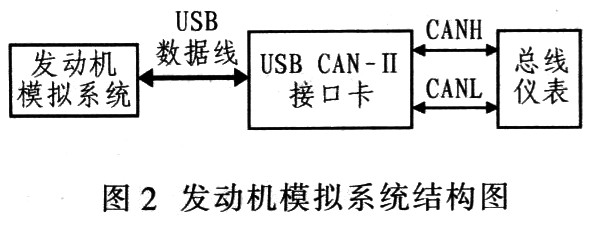
3 system design scheme The engine simulation system transmits data to the bus instrument CAN interface card through the USB CAN-II intelligent interface, and the bus instrument responds to the analog system through the USBCAN-II interface card, as shown in Figure 2. The system is designed to run under the C# environment and run on the Windows platform. The system is designed with main function modules such as engine parameter messages, engine fault messages, engine instrumentation tests, and optional transmission methods for single or multiple frames. By calling the USBCAN-II interface card library port function, the communication between the upper computer and the lower computer is realized by CAN bus transmission, and various parameters of the engine, such as coolant temperature, intake air temperature, oil pressure, etc., can be simulated, and virtual The meter evaluates the error of the bus meter stepper motor.
The USB CAN-II dual intelligent CAN interface card has 2 CAN channels (automobile type). It features a 16-bit microcontroller with powerful features that support plug and play. The on-board 16-bit microcontroller can control the CAN controller's transmit and receive tasks, effectively supporting the filtering, pre-processing and storage of CAN messages with time stamps and CAN reports even in heavy-duty bus loads. Real-time transmission of text and other functions. By calling the USB CAN-II auxiliary general CAN-bus interface function library, it can effectively support PC-based applications of CAN system. The programming flow chart is shown in Figure 3.
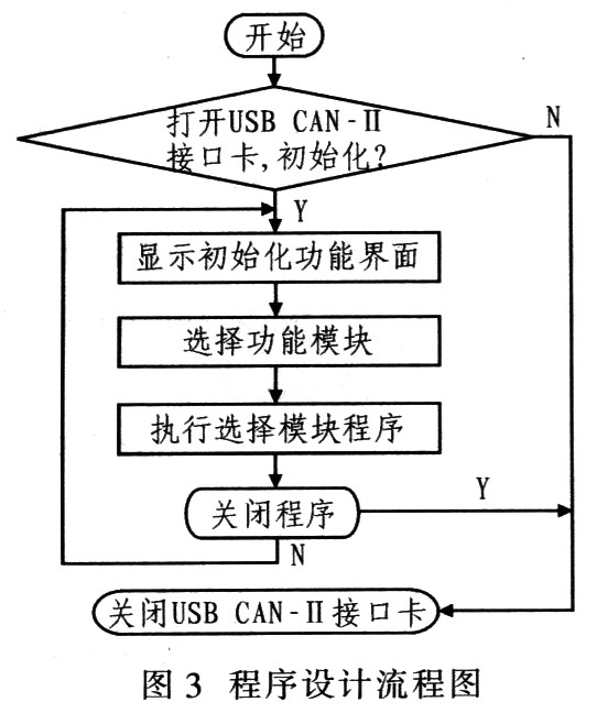
C# call interface library function methods: (1) put the library function file in the working directory; (2) declare using System. Runtime. InteropServices; (3) declare the data type of the ZLGCAN series interface card information; (4) import, to open the device function as an example, other functional function references are similar. Open the device function as: 
4 Engine simulation system design The system is divided into engine parameter message, engine fault message and engine instrument test according to function. In order to facilitate the separate use of each functional interface, a composite interface form is adopted. Its running interface is shown in Figure 4.
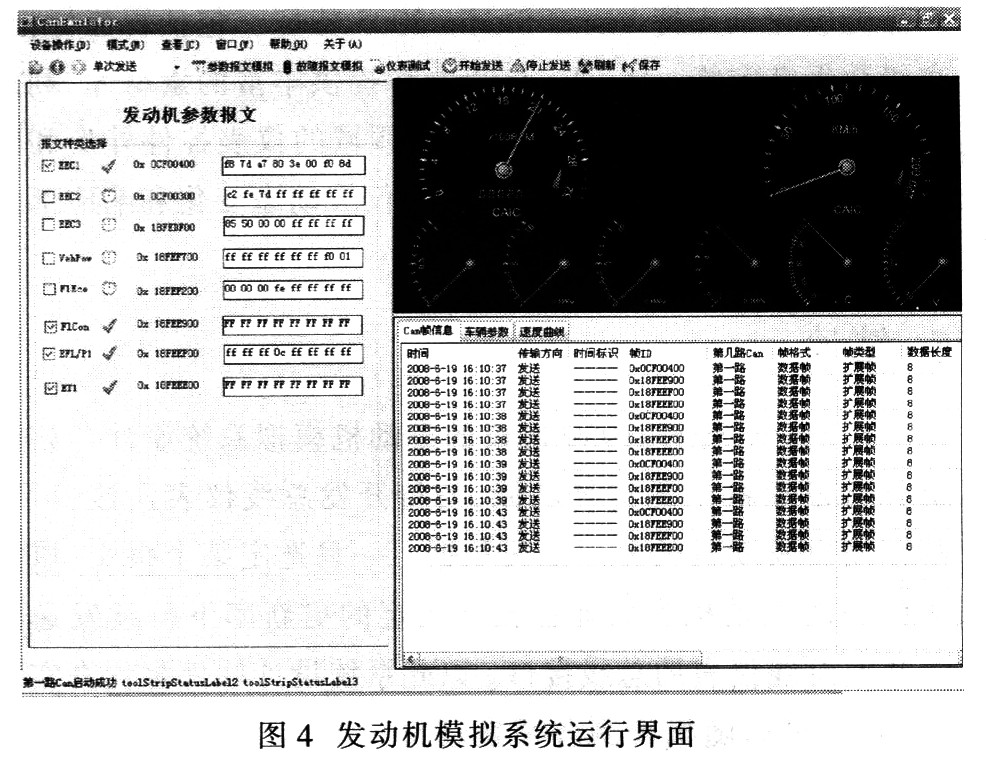
4.1 Engine Parameter Message Transmitting Module This module is a set of data for analog field test. According to SAE J1939 CAN communication specification for Euro III engine for BOSCH high pressure common rail system, the frame ID and the data word representing the engine parameters. The section position corresponds, and the parameter value to be sent can be changed by modifying the relevant byte.
If you want to send a speed of 2 000 r / m, the data is in the 4th and 5th bytes of the message. The 4th and 5th bytes of the transmitted data are 2 000/0.125 = 16 000 converted to two bytes, note that the high byte is placed in the 5th byte and the low byte is placed in the 4th byte. The same table can be used to calculate other engine parameters, such as lubricant pressure, coolant temperature, battery voltage, fuel level, ECU temperature, intake air temperature, oil pressure, throttle position and other parameter values ​​corresponding to the frame ID and data. The position of the frame.
4.2 Engine fault message sending module When the engine fails, the data collected by the sensor is analyzed and processed by the EMR single chip microcomputer to determine whether the collected data is within the normal range or valid. If the data is not in the normal range or is invalid, the EMR will send a fault frame to the host computer, indicating that the corresponding component of the sensor is faulty. The bus instrument designed by the system adds fault diagnosis function, and can display the fault type of the engine in real time by means of the liquid crystal display.
In terms of troubleshooting, SAE J1939 defines 19 Diagnostic Messages (DMs). The fault message sending module mainly adopts the DM1 (display current fault) function. The DM consists of a diagnostic fault light code (2 bytes) and a diagnostic trouble code DTC (4 bytes). The diagnostic trouble code DTC has a length of 4 bytes, including the suspect parameter code SPN (19 bits), the fault type code FMI (5 bits), the number of failure occurrences OC (7 bits), and the SPN conversion mode CM (1 bit).
The system design defines more than 400 faults, and defines the fault type code FMI and SPN. The definition follows the principle that the combination of SPN and FMI corresponds to the fault type.
4.3 Engine Instrumentation Test Module The engine instrumentation test module compares the running speed of the virtual instrument with the development instrument and tests the stepper motor drive of the development instrument. Since only the instrument data such as speedometer, oil pressure gauge, water temperature gauge and voltmeter are provided by the engine CAN bus, the test instrument can only simulate the stepping motor drive of the four dials. The test instrument uses the Dundas Instrument Wizard, which fully supports Visual Studio 2005 features, including smart tagging, advanced data binding, and more. The Dundas Meter Wizard provides a rich library of materials that allows users to design instrument control shapes and data indications for a variety of applications. The user only needs to write the relevant meter dynamic change and response part code to implement the virtual instrument function.
5 Conclusions The design of the engine simulation system based on the SAE J1939 protocol is introduced. The system has engine operating condition selection function, which is connected with the bus instrument to be developed, and can simulate and output various working condition data of the engine. Once a message is selected, the engine parameters represented by the message are continuously sent to the bus interface of the bus instrument to be developed under the update rate specified by the message. This system design software replaces the real engine, can randomly detect various engine operating conditions, and has the flexibility of artificial selection, the selection range is larger than the real engine. The online simulation system is not limited by the working environment and can be tested anytime and anywhere. The system is part of a laboratory test system for the laboratory and can also be used in conjunction with teaching experiments. Through experiments, all parts of the software function well, which has certain value for bus instrument development. With the continuous development of the CAN bus application field, the SAE J1939 protocol is bound to be widely used.
Box Header
Box Header
ATKCONN ELECTRONICS CO., LTD , https://www.atkconn.com