Figure 9-48 shows the diode detection circuit. VD1 in the circuit is a detector diode, C1 is a high frequency filter capacitor, R1 is the load resistance of the detector circuit, and C2 is a coupling capacitor.
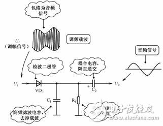
Figure 9-48 Diode Detector Circuit
1. Circuit analysis preparation knowledgeAs we all know, the radio has two kinds of AM radio and FM radio. The AM signal is the signal processed and amplified in the AM radio. See the schematic diagram of the amplitude modulation signal waveform in the figure. The following points are mainly explained for this signal waveform:
(1) From the amplitude modulation radio antenna is the amplitude modulation signal.
(2) The middle part of the signal is a carrier signal with a very high frequency. Its upper and lower ends are the envelope of the amplitude modulation signal, and its envelope is the required audio signal.
(3) The upper envelope signal and the lower envelope signal are symmetrical, but the signal phase is opposite. The radio finally needs only the upper envelope signal, the lower envelope signal is not used, and the middle high frequency carrier signal is not needed.
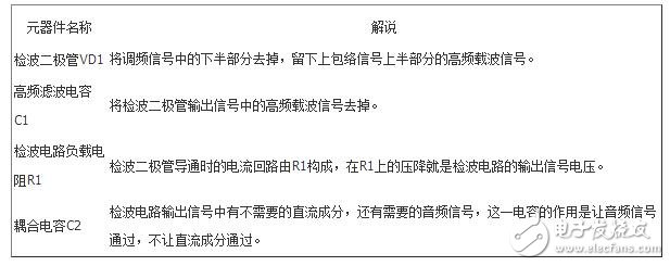
2. Description of the functions of each component in the circuitTable 9-43 shows the function of the components.
Table 9-43 Explanation of component functions
Pond Frequency Pumps,Submersible Filtration Pump,Various Fountain Heads Pump,Pump With Asynchronous Motor
Sensen Group Co., Ltd.  , https://www.sunsunglobal.com