The optocoupler introduced here is a combination of a light-emitting diode and a phototransistor. The light-emitting diode converts the electrical signal on the input side into the same regular change of light, and the optical pulse-sensitive transistor re-converts the light into the same change law. The electrical signal, therefore, the light acts as a medium. Due to the strong anti-interference ability of the optocoupler, it is easy to complete level matching and transfer, and is not limited by whether the signal source is grounded. So the application is increasingly widespread.
1. A multi-resonant circuit composed of a photocoupler composed of a multi-resonant circuit composed of a photocoupler is shown in Fig. 1.
When the power supply Ec is just turned on in Fig. 1(a), since the UF increases with C charging, until the UF ≈ 1 volt, the LED is saturated, and then the triode is also saturated, and Uo ≈ Ec is output.
After the triode is saturated, C discharge (discharged by C→F→E1→Er and from C→RF→+Ec→Re), uo decreases, and the diode is turned off after C discharges to a certain extent, and the triode is stored. After the charge is completely removed, it is also turned off, and uo is zero. After the triode is turned off, the power supply Ec charges C again, and the above process is repeated to obtain the peak output waveform of the figure, and its period is (when RF Re):
T=C(RF+Re)In2
Figure 1 (b) is another form of circuit of the same principle.
Explain the output Ei measured voltage, send it to the encoder for sampling and measurement after chopping. When point A is low and point B is high, GD1 is turned on, GD2 is turned off, and the measured voltage Ei is directly sent to the output. Terminal, on the contrary, point A is high, point B is low, GD1 is off, GD2 is on, C is discharged by GD2, and the output is returned to zero.
More accurate than ordinary transistor or FET chopper. When CB pulse is input, BG is turned on, then GD is turned on, ui of input side is transmitted to output side, and uo is proportional to ui but opposite phase, otherwise When the chopping pulse is zero, GD is cut off, uo is high level, and the modulator is isolated from the ordinary transformer, and the precision is high. Because the transformer voltage is not too large, the output pulse wave top is not flat. Use two GD1 and GD2. Among them, GD1 is used as a switch. When the chopping pulse is input, GD1 is turned on, and ui is inverted to the output side of GD2, so that uo is isolated from input ui and chopping pulses.
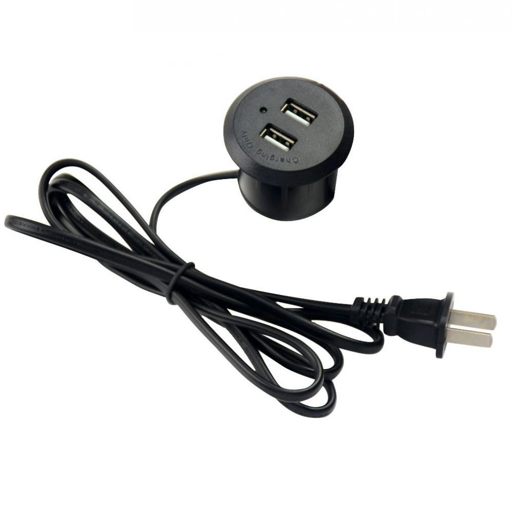
Beyond the traditional charger, more than a little bit. High power, voltage detection, fast charging, intelligent chip, high security. Multiple charging ports are extended to meet requirements. More interfaces, compatible with more electrical appliances. Even if you're in a car, don't worry. Compact size, where is comfortable. Safety protection, plug built-in fuse, protect electrical appliances from overload and short circuit damage. We are the leading manufacturer and supplier of double USB chargers and round USB chargers in China. We specialize in USB socket, round Usb Charger and so on. Welcome to consult.

Dual USB Charger,Round USB Charger,USB Charger Outlet,Round USB Charging
Dongguan baiyou electronic co.,ltd , https://www.dgbaiyou.com