High-voltage direct current transmission: The three-phase alternating current is rectified into a direct current through a converter station, and then sent to another converter station through a direct current transmission line to be converted into a three-phase alternating current transmission mode.
The schematic diagram of HVDC transmission is as follows:
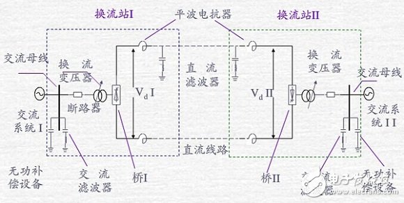
Inverter (rectifier or inverter): A device that converts AC power into DC power or converts DC power into AC power.
Converter transformer: Provides an appropriate level of ungrounded three-phase voltage source equipment to the inverter.
Flat-wave reactor: reduce the harmonics injected into the DC system, reduce the probability of commutation failure, prevent DC current interruption during light load, and limit the DC short-circuit current peak.
Filter: A device that reduces the harmonics injected into the AC and DC systems.
Reactive power compensation equipment: provides the reactive power required by the inverter, and reduces the reactive power exchange between the inverter and the system.
HVDC transmission vs. AC transmission:
1) Technical
Power transfer characteristics. In order to meet the stability problem, it is often necessary to adopt measures such as series compensation and static compensation, and sometimes even have to increase the transmission voltage. A lot of electrical equipment will be added and it will be expensive. There is no phase and power angle for DC transmission, and there is no need to consider stability. This is an important feature of DC transmission and a major advantage.
Self-protection capability when the line is faulty. After the AC line is single-phase grounded, the elimination process is generally about 0.4~0.8 seconds, plus the reclosing time, about 0.6~1 second recovery. The DC line is single-pole grounded, and the thyristor valves on both sides of the rectification and inverter are immediately locked. The voltage drop is zero, forcing the DC current to drop to zero. The fault arc is extinguished. There is no difficulty that the current cannot cross the zero. The recovery time of the DC line unipolar fault is generally Within 0.2~0.35 seconds.
Overload capacity. AC transmission lines have a high continuous operation capability, and their maximum transmission capacity is often controlled by the stability limit. The DC line also has a certain overload capacity, and the converter station is often restricted. Usually divided into 2 hours of overload capacity, 10 seconds of overload capacity and inherent overload capacity. The first two DCs are 10% and 25%, respectively, and the latter varies depending on the ambient temperature. In terms of overload, communication has more flexibility. If DC needs more overload capacity, it should be considered in the selection of equipment, and it is necessary to increase investment.
Current and power control. AC transmission depends on network parameters, generator and load operation mode, on-duty personnel need to schedule, but difficult to control, DC transmission can be fully automatic control. The DC transmission control system has fast response, precise adjustment, convenient operation and multi-target control.
Short circuit capacity. When the two systems are interconnected, the short-circuit capacity of the systems on both sides will increase, and sometimes some of the original circuit breakers will not meet the breaking capacity requirements and need to be replaced. When DC interconnection occurs, no matter where the fault occurs, the current increased on the DC line is not large, so the disconnection capacity of the AC system is not increased.
cable. Cable insulation for DC allows the operating voltage to be twice as high as that used for AC. For example, a 35kV AC cable is allowed to operate at a DC voltage of around 100kV, so the DC cable cost is the same when the DC operating voltage is the same as the AC operating voltage. Far less than the AC cable.
Comparison of power loss of transmission lines. In direct current transmission, the voltage distribution along the direct current transmission line is stable, and there is no capacitive current. Under the condition that the cross-sectional area of ​​the conductor is the same and the useful power is equal, the power loss of the DC line is about 2/3 of that of the AC line. And no parallel reactance compensation is needed.
Line corridor. Considering the same voltage of 500kV, the corridor of a 500kV DC transmission line is about 40m, and the corridor of a 500kV AC line is about 50m, but the transmission capacity of a DC line with the same voltage is about twice that of AC, and the transmission of the line corridor of the DC transmission is transmitted. The efficiency is about 2 times or more than the AC line.
In general, the following factors limit the application range of HVDC: the transformer can not be used to change the voltage level; the cost of the converter station is high; the control is complicated.
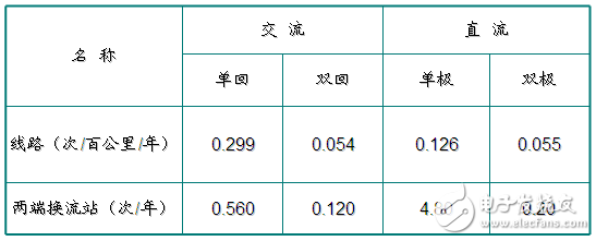
2) Reliability
Forced outage rate
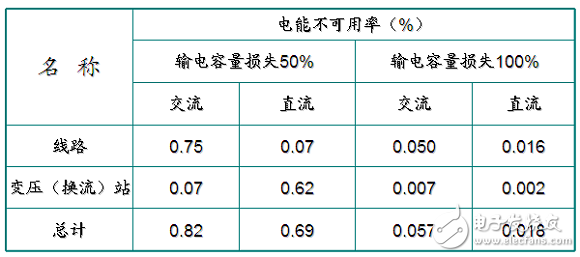
Power unavailability
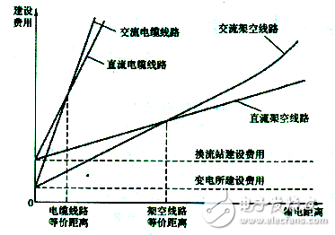
3) Economics
As far as the two parts of the substation and the line are concerned, the investment in the HVDC converter station accounts for a large proportion, while the investment in the transmission line of the AC transmission is the main component;
DC transmission power loss is much smaller than AC transmission;
When the transmission power is increased, the direct current transmission can adopt a method of increasing the voltage and increasing the cross section of the conductor, and the alternating current transmission often has to increase the number of circuits.
Under a certain transmission distance, the total cost of the two is equal, and a distance is called the equivalent distance. This is an important preliminary estimate of the project. When this distance is exceeded, DC is advantageous; when it is less than this distance, it is advantageous to use AC.
HVDC transmission classification:
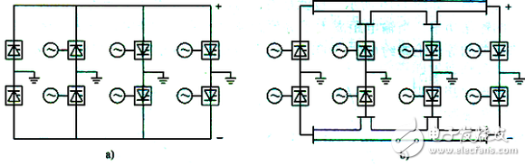
1) Both ends HVDC system: A DC transmission system consisting of two converter stations. Divided into unipolar, bipolar and back-to-back, the first two are well understood, mainly back-to-back DC.
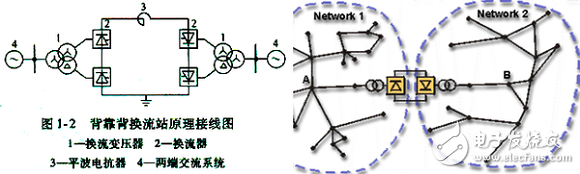
Back to back DC:
HVDC system without DC line.
It is mainly used for networking or power transmission between two asynchronous power systems, also called asynchronous contact stations.
The equipment of the rectifier station and the inverter station is usually installed in a station, also called a back-to-back converter station.
The DC side can select low voltage and large current; the DC side harmonic will not cause interference of the communication line; the cost is reduced by about 15% to 20% compared with the conventional converter station.
2) Multi-terminal direct current transmission system (MTDC): When the DC system is connected to more than two nodes on the AC grid, it constitutes a multi-terminal high-voltage DC system.
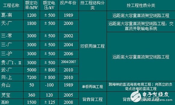
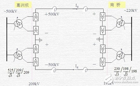
At present, there are still many high-voltage direct current transmission projects in China.
The principle of the inverter is not developed. Many power electronic contents mainly summarize the DC transmission control method.
The objectives of the DC transmission control system are:
1) keep the DC power, voltage, current and control angle within the steady-state value range;
2) Limiting transient overvoltage and overcurrent;
3) After the AC/DC system fails, the power transmission is smoothly resumed within the specified response time.
The main advantage of DC systems is control, which is also more complicated.
Basic control module for DC transmission:
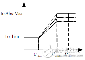
Low-Voltage Current Limit Control (VDCOL): The task of the low-voltage current-limit link is to limit the DC current command when the DC voltage or AC voltage drops to a certain command value.
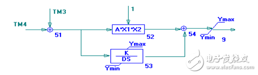
Constant Current Control (CCA): Constant current control is the most widely used in pole control functions. The control block diagram of constant current control is shown in the figure. On the rectification side, the input of the constant current controller is the deviation of the current setting value TM3 from the actual current TM4.
Constant arc extinction angle control (AMAX): The extinction angle of most DC projects is within the range of 15 ° ~ 18 °. The arc extinction angle can be directly measured, but can not be directly controlled. The trigger angle of the inverter is adjusted indirectly. The extinction angle is not only related to the firing angle of the inverter side, but also depends on the magnitude of the commutation voltage and the DC current.
Constant voltage control (VCAREG): The constant voltage control function module is set in both rectification and inverter mode. The function of this controller is for buck operation, but it is also beneficial for normal mode operation. Its control is also used. PI adjustment method.
Auxiliary control module:
Tap Control (TCC): The purpose of tap control is to keep the firing angle, arc extinction angle, and DC voltage running within the specified range. The tap control is characterized by slower regulation.
Reactive Power Control (RPC): Different DC engineering, filters and capacitors are divided into several groups, which are switched by the power switch.
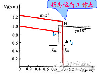
Under normal circumstances, 1) When the voltage fluctuations in the AC systems on both sides are not large, the rectification side adopts constant current control, and the inverter side adopts constant arc extinction angle control. 2) In order to adjust the power quickly and accurately, the rectifier side adopts constant current control (or constant power control), and the inverter side adopts constant DC voltage control.
The reason is that the constant current control on the rectification side can control the trigger angle to change according to the load, and the constant voltage control keeps the trigger angle of the inverter side constant, so that the transmission current, that is, the power transmission size can be controlled by the rectification side firing angle. However, when the rectification side trigger angle reaches the minimum value (about 5°), the constant current control cannot be continued. The rectification side firing angle can only be constant, and it will become constant voltage control.
This piece is closely related to the operation, the content inside is quite complicated, and I am not particularly familiar with it, just sum up a fur.
Third, some points of analysis of HVDC transmission system1) Commutation failure
Commutation failure is a critical and common failure of DC systems.
When the inverter is operated in an inverter, the angle corresponding to the time from the zero-crossing of the valve current to the commutation to the time when the valve is re-applied with the forward voltage is also called the cut-off angle (arc-cutting) angle). If the turn-off angle is too small, so that the thyristor valve does not fully recover its normal blocking capability and is re-applied with a forward voltage, it will automatically turn back on, and a reverse commutation process will occur, the result of which will be the turned-on valve. Shut off, and the valve that should be turned off continues to conduct, called commutation failure.
The main reason for the failure of the commutation is the failure of the AC system, which causes the inverter side converter bus voltage to drop. Under certain conditions, some commutation failures can be automatically restored. However, if two or more consecutive commutation failures occur, the converter valve will be blocked, interrupting the transmission channel of the DC system. In severe cases, multiple inverter stations may fail to commutate at the same time, or even cause the grid to collapse. .
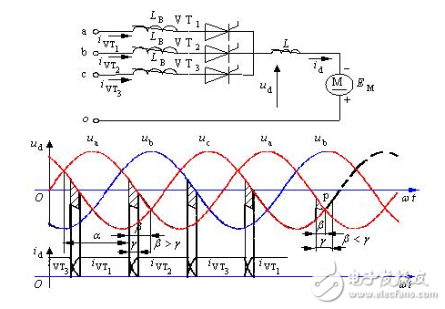
The effect of the commutation overlap angle: When β γ, at the end of the commutation, the thyristor can withstand the back pressure and turn off. If β “γ†(as clearly seen from the waveform in the lower right corner of the figure), the pass thyristor (VT2) will be turned off, and the thyristor (VT1) that should be turned off cannot be turned off, eventually causing the inverter to fail.
2) Reactive power compensation
The reactive power calculation of the DC system is also divided into two parts: conventional calculation and system simulation.
The high-voltage direct current transmission converter station that uses the common thyristor converter valve for commutation generally adopts the power grid commutation control technology, which is characterized in that the converter needs to draw a large amount of reactive power from the AC system during operation. In proportion to the active power exchanged, the reactive power required by the rectifier in rated operating conditions is approximately 30% to 50% of the active power, and the inverter is approximately 40% to 60%.
For conventional calculations, the reactive power consumed by the inverter can be expressed by:
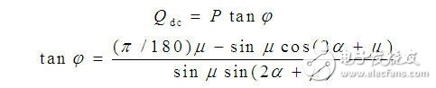
P is the DC side power of the converter, MW; φ is the power factor angle of the converter; μ is the commutation angle; α is the rectifier firing angle. When the inverter is operated in an inverter mode, α in the equation is replaced by γ, and γ is the inverter side turn-off angle.
Of course, in the specific project, the reactive power configuration also involves the comparison of various reactive power grouping schemes. Both sensibility and capacitiveness should be considered. However, in general, sensible reactive power mainly considers the small load mode of reactive excess, and often it is calculated not. Need to match.
Then it is the system simulation check work, which is to use the power software to simulate the steady state and transient operation under various working conditions, and the stability under the fault mode.
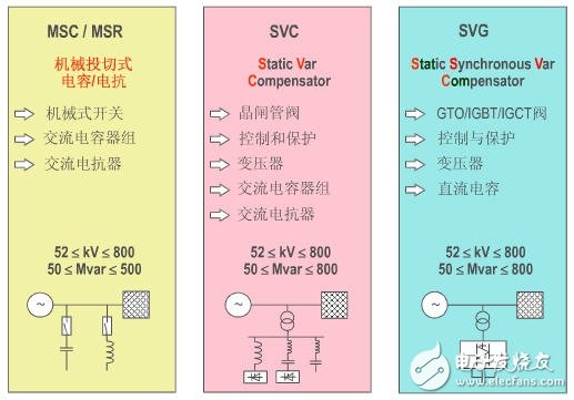
The most economical way to provide the required reactive power is to use a shunt capacitor bank. Since reactive power varies with the transmitted DC power, it is necessary to provide a switchable capacitor bank of the appropriate capacity so that the steady state DC voltage remains within an acceptable range (typically ± 5%) at various load levels. If the generator is near the DC terminal, it is useful to handle part of the reactive power demand and keep the steady state voltage within an acceptable range. For weak AC systems, it may be necessary to provide reactive compensation with a static var compensator (SVC) or a static synchronous compensator (STATCOM).
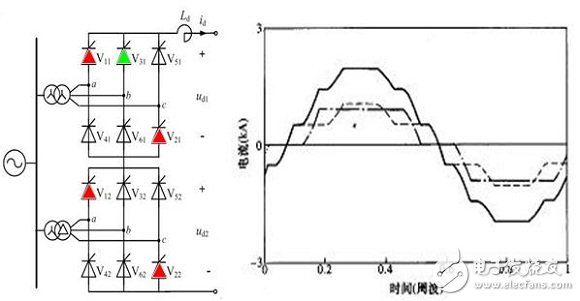
3) Harmonic suppression
The inverter generates higher harmonics on both the AC side and the DC side. The commutation device is a harmonic current source for the AC side and a harmonic voltage source for the DC side. The AC side characteristic harmonics are exemplified as follows.
Under ideal operating conditions, the system has characteristic harmonics. However, the operating conditions of the actual DC transmission project may not be ideal, so there are also non-characteristic harmonics.
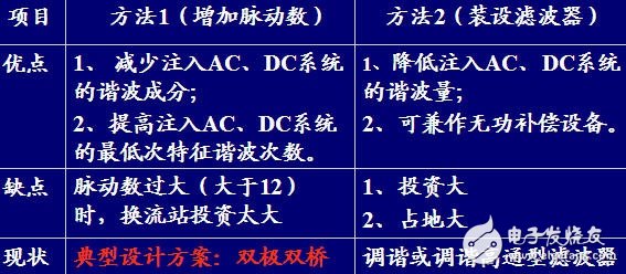
There are two main types of harmonic suppression measures at converter stations:
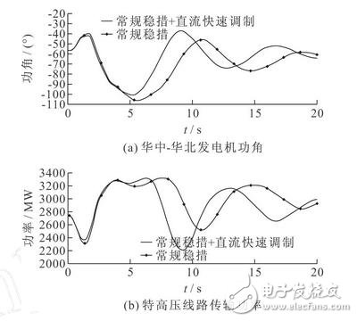
4) DC modulation
The modulation function of the HVDC transmission system is a control function of the system control level.
It utilizes some parameters of the AC system connected to the DC transmission system to adjust the DC power or DC current, DC voltage, and reactive power absorbed by the inverter, so as to fully utilize the DC system power for rapid controllability and improve the AC system. Running performance. Whether a DC transmission system needs to design a certain modulation function depends entirely on the needs of the AC system to which it is connected, so each project may be different. Commonly used modulation functions are: (1) power boost (or fallback), (2) frequency control, and (3) damping control.
Simply summarize these four modulations.
Power boost (or fallback): When the receiving end (or the transmitting end) AC grid is seriously faulty, it may be required that the DC system rapidly increase (or reduce) the delivered DC power to support the receiving end (or sending end) grid. This modulation function is also called emergency power support.
Frequency control: Utilize the rapid controllability of the power of the DC transmission system, adjust the frequency of the AC system connected to one or both ends, and jointly utilize the thermal reserve capacity of the AC system at both ends.
Damping control: This project is still concerned about the use of power for rapid controllability for group control. For example, the subsynchronous oscillation in the AC system connected to the damping, damping the low frequency power oscillation, and the like. The main process is as follows:
This piece is mainly two parts, and it may not be enough to cover it, so there should be other content.
1) UHV DC transmission
The controversy surrounding the exchange of UHV has continued for years, and the National Grid, which promotes the exchange of UHV, believes that the project has obvious advantages and can solve problems such as new energy consumption, regional power resource balance and smog control; opponents believe that ±500 thousand Volt high voltage and DC ultra high voltage can completely solve the above problems. The exchange of UHV economy is poor and there are hidden dangers. It is not suitable for construction. But there is a point on both sides that is consistent, that is, UHV DC transmission is a very good transmission method.
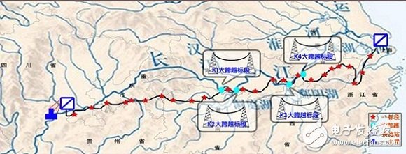
There are also many UHV DC lines that are put into operation and under construction, such as ±800kV Yunguang, Upward, Jinsu, and Hazhen Line. The following picture shows the path of the up line (Xiangjiaba-Shanghai)
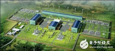
The system configuration of UHVDC is the same as that of HVDC transmission, but the number of single bridges, the transmission capacity, the capacity of electrical primary equipment and the insulation level are quite different.
2) Lightweight DC transmission technology
Light-weight direct current transmission: the voltage source converter (VSC) is the core, the hardware uses IGBT and other shut-off devices, and the pulse-width modulation technology (PWM) is used for control to achieve high controllable DC transmission.
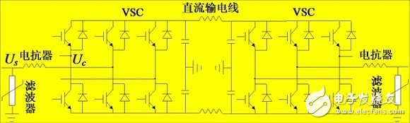
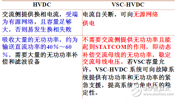
Due to the application of VSC, the differences between VSC-HVDC and HVDC are as follows:
The control method of VSC-HVDC is still relatively mature. At present, the research mainly focuses on the topology, such as multi-level, etc. (it is also possible that my information is not enough front), such as modular multi-level converter (MMC).
The application prospects of VSC-HVDC are still very wide. Individuals are most optimistic about the application of new energy grid-connected and central city power grids.
ZGAR AZ BOX Vape
ZGAR electronic cigarette uses high-tech R&D, food grade disposable pod device and high-quality raw material. All package designs are Original IP. Our designer team is from Hong Kong. We have very high requirements for product quality, flavors taste and packaging design. The E-liquid is imported, materials are food grade, and assembly plant is medical-grade dust-free workshops.
Our products include disposable e-cigarettes, rechargeable e-cigarettes, rechargreable disposable vape pen, and various of flavors of cigarette cartridges. From 600puffs to 5000puffs, ZGAR bar Disposable offer high-tech R&D, E-cigarette improves battery capacity, We offer various of flavors and support customization. And printing designs can be customized. We have our own professional team and competitive quotations for any OEM or ODM works.
We supply OEM rechargeable disposable vape pen,OEM disposable electronic cigarette,ODM disposable vape pen,ODM disposable electronic cigarette,OEM/ODM vape pen e-cigarette,OEM/ODM atomizer device.


ZGAR AZ BOX Vape,ZGAR AZ BOX disposable electronic cigarette,ZGAR AZ BOX Vape vape pen atomizer , AZ BOX Device E-cig,AZ BOX disposable electronic cigarette
ZGAR INTERNATIONAL(HK)CO., LIMITED , https://www.szvape-pen.com