A power filter is a filter circuit consisting of a capacitor, an inductor, and a resistor. It is also known as a "power EMI filter" or an "EMI power filter." A passive two-way network that has a power supply at one end and a load at the other end. . The principle of the power filter is one - impedance matching network: the greater the impedance adaptation between the input and output sides of the power supply filter and the power supply and load side, the more effective the attenuation of electromagnetic interference is. The filter can effectively filter out the frequency of a specific frequency in the power line or a frequency other than the frequency to obtain a power signal of a specific frequency or eliminate the power signal after a specific frequency.
The working principle and function of the power filter:The filter circuits commonly used in filters are passive filtering and active filtering. The main forms of passive filtering are capacitive filtering, inductive filtering and complex filtering (including inverted L-type, LC filtering, LCÏ€-type filtering and RCÏ€-type filtering, etc.). The main form of active filtering is active RC filtering, also known as electronic filters. The magnitude of the pulsating component in the direct current is represented by the pulsation coefficient S. The larger the value, the worse the filtering effect of the filter.
Pulsation coefficient (S) = fundamental maximum of output voltage AC component / DC component of output voltage
The principle of the line filter is an impedance matching network: the greater the impedance adaptation between the input and output sides of the line filter and the power supply and load side, the more effective the attenuation of electromagnetic interference is.
The specific working principle is as follows: After the alternating current is rectified by the diode, the direction is single, but the size (current intensity) is still constantly changing. This pulsating DC is generally not directly used to power the radio. To turn the pulsating DC into a waveform-smooth DC, you need to do another "filling in" work, which is filtering. In other words, the task of filtering is to reduce the fluctuation component of the rectifier output voltage as much as possible, and transform it into a nearly constant DC power.
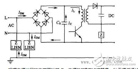
According to the electromagnetic disturbance characteristics of the power port, the power supply EMI noise filter is a passive low-pass filter that transmits AC power to the power supply without attenuation, and greatly attenuates the EMI noise transmitted with the AC, and at the same time effectively suppresses The EMI noise generated by the power supply devices prevents them from entering the AC grid and interfering with other electronic devices.
The typical structure of the line filter is shown in the figure below. This is a passive network structure that is suitable for both AC and DC power supplies and has bidirectional suppression. Insert it between the AC grid and the power supply, which is equivalent to adding a blocking barrier between the EMI noise of the two, so that a simple passive filter acts as a two-way noise suppression, thus in various electronic A wide range of applications are available in the device.
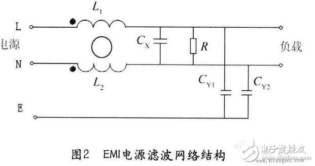
In the figure, Cx is a differential mode capacitor, generally called X capacitor. The capacitance should be chosen to be 0.01-2.22μF. CY1 and CY2 are common mode capacitors, generally called Y capacitors. The capacitance is about a few nanofarads (nF) to several. Ten nano law. The capacitance of C3 and C4 should not be too large, otherwise it will easily cause the risk of leakage of filters and even casings. L is a common mode choke coil, which is a pair of coils wound in the same ferrite ring in the same direction, and the inductance is about several millihenries (mH). For the common mode interference current, the magnetic fields generated by the two coils are in the same direction, and the common mode choke coil exhibits a large impedance, thereby attenuating the interference signal; and for the differential mode signal (here is the low frequency supply current) ), the magnetic field generated by the two coils cancels, so it does not affect the power transmission function of the circuit.
The power filter is designed for the characteristics of electromagnetic interference of the power port. It is generally a frequency selective two-port network composed of an inductor, a capacitor, a resistor or a ferrite device. It is actually a type of filter, which is called according to the working principle. It is a reflective filter. It provides a high series impedance and low parallel impedance within the filter stopband, which severely mismatches the impedance and load impedance of the noise source, thereby transmitting unwanted frequency components back to the noise source.
When we choose the power filter, we should mainly consider three aspects: first, voltage and current, then insertion loss, and finally structure size. Since the interior of the filter is typically potted, environmental characteristics are not a major issue. However, the temperature characteristics of all potting materials and filter capacitors have an effect on the environmental characteristics of the power supply filter.
Filter selection, how to choose the correct filter:A filter is a device used to eliminate interfering noise. The input or output is filtered to obtain pure DC power. A circuit that effectively filters out frequencies at a particular frequency or frequencies outside of that frequency is a filter whose function is to obtain a particular frequency or to eliminate a particular frequency.
Filter selectionHow do circuit designers determine which filter to use in which situation? This article is intended to help them make this decision.
The choice of filter looks mysterious, but it is not. However, on many occasions, even if you try your best to choose the method described below, you still need to experiment with multiple filters to pick the most suitable one.
So why bother to choose the right filter? Filtering the filters according to the guidelines provided here, at least to meet the correct size and type requirements of the filter, therefore, the trial filter simply replaces the other filter with one filter and checks for conducted and radiated emissions. See which filter has the best cost-effectiveness ratio.
If you don't have enough patience to choose a filter during the design process, Murphy's Law (as if all physical, medical, and financial formulas are derived from it) shows that the most appropriate filter will eventually prove to be Other requirements for the product are completely incompatible. Either the filter is too large or too heavy to fit in the mold cavity, requiring an expensive remanufacturing of the mold, either an unsuitable installation method or a leakage current from the filter. Products that are introduced to the market have security risks. Indeed, if you do not carefully select the correct model and type of filter, then according to Murphy's Law, selecting the right filter will increase the development and production costs, and will also delay the time to market.
1. Calculation of filter related indicatorsBy comparing the emission spectrum of the product with the relevant EMC standards, it is possible to estimate the amount of attenuation required to control the emission with a filter. For immunity control, a rough value can be estimated by comparing external electrical noise (usually taken from the relevant EMC immunity criteria) to the sensitivity of the product electronics and the desired level of performance during the disturbance.
When the actual emission or sensitive performance of a product is clearly known, accurate calculations can be taken without estimation. However, if you are not working in a controlled 50Ω impedance environment, the manufacturer's product specifications are unreliable when purchasing filters.
2. Impedance problemThe working principle of the filter is to form a large characteristic impedance discontinuity in the transmission path of the radio frequency electromagnetic wave, and reflect most of the energy in the radio frequency electromagnetic wave back to the source. The performance of most filters is measured with a source and load impedance of 50, which leads us to the very important point that the performance of the filter is not optimal under practical conditions.
Consider a typical power line filter that is installed between the AC power line and the AC-DC converter that is the DC power source for electronics. During the day, the impedance of the AC source varies between 2 and 2 kΩ, depending on the load connected to it and the frequency of interest. The characteristic impedance of the power line connected to the electronic device is approximately 150 Ω. When the rectifier is turned on near the spike of the power supply waveform, it is equivalent to a short circuit, and at other times, it is equivalent to an open circuit.
Filter parameters were obtained in a 50 Ω source and load impedance test environment because most RF test equipment uses 50 Ω sources, loads, and cables. The filter performance parameters obtained by this method are optimized and are also the most misleading.
Since the filter consists of an inductor and a capacitor, this is a resonant circuit. Its performance and resonance mainly depend on the impedance of the source and load terminals. In fact, an expensive filter with 50/50 performance may not perform as well as a lower-cost filter with 50/50 performance.
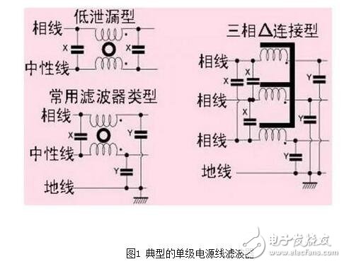
3. Power line filterThe single-stage power line filter shown in Figure 1 is sensitive to both source and load impedance. When operating under actual source and load impedance conditions, it is easy to generate gain rather than attenuation. This gain typically occurs in the frequency range of 150 kHz to 10 MHz and can range from 10 to 20 dB. Therefore, installing an inappropriate filter on the product may increase the emission intensity and/or make the sensitivity worse.
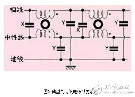
The two or more stages of the filter shown in Figure 2 keep the internal contacts at a relatively stable impedance, so the impedance dependence on the load and source is not very large and can provide performance close to the 50/50 specification. Of course, these filters are larger and more expensive.
In order to solve the impedance problem, it is best to purchase the manufacturer and also indicate the indicators in the "matched" 50/50 test system and the products under the "mismatch" conditions. The mismatch data was measured under conditions of source impedance of 0.1 and load impedance of 100, and under the opposite conditions. One trick is to use a worst-case scenario in all of these curves to form an attenuation curve and use it as a technical indicator for the filter. When this method is used to select a filter to meet the intended purpose of the product, the performance of the filter is usually able to achieve the desired effect, or even better.
Most power line filters use a common mode choke and an X capacitor connected between the phase lines to handle differential mode interference. If the filter is used to solve the problem of low-frequency high-intensity interference generated by circuits such as switching power supplies, phase angle power controllers, and motor drivers, it usually requires more attenuation than the differential mode attenuation that the X capacitor can provide. Differential mode choke shown in 3. Since the magnetic core is saturated, it is difficult to obtain a large inductance in a small volume. These filters are generally bulky and expensive.
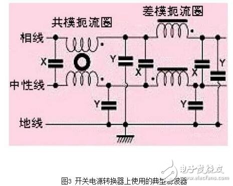
Most power line filters use Y-type capacitors that are connected between the phase and ground. In order not to exceed the ground allowable leakage values ​​defined by the relevant safety standards, the values ​​of these capacitors are around a few nF. In general, the Y capacitor should be connected to a conductor with high noise interference (for example, a power line in a meter-sensitive analog circuit, a rectifier in a switching power supply, etc.).
For medical equipment, especially in contact with the patient's body, the ground leakage current value is required to be quite low, so using any type of Y-type capacitor is not acceptable. The filters used at this time require greater inductance and/or multi-stage cascades, so they are larger and more expensive. (It is best to use battery power at the end of the device connected to the patient and connect it to the AC powered device only through optocouplers or fiber optics.)
In larger systems, ground leakage from a large number of small Y-type capacitors can generate large ground currents, which can cause ground-line voltage differences, resulting in "å—¡å—¡" on interconnected cables between different devices. The hum and transient high level. The modern best solution is to use an equipotential three-dimensional ground connection, but this is not possible with many old facilities. Therefore, devices that are used in large systems should use filters with small or no Y capacitance.
It is best to use a power line filter that meets safety certification. The safety, reliability, temperature range, voltage rating and current rating of these filters, as well as the application of appropriate safety standards, have been certified by the manufacturer.
4. Signal line filterIf the conducted or radiated emissions are caused by the unavoidable signal spectrum, then attempting to use differential mode filters to reduce these emissions is not the way. However, common mode filtering is possible for frequencies within the spectral range of the signal of interest, since the useful signal is differential mode rather than common mode.
In the technical specifications of the signal line filter, the ground line noise is generally ignored. The driver chip will generate ground jump noise. If the ground plane between the digital printed circuit board and the chassis is not well connected, a large amount of digital 0V noise will be generated in all the wires. Therefore, the outer package is marked with low noise. The slew rate of the driver chip may still generate high level RF noise.
Filters used in low-frequency analog signals, especially when the sensitivity of electronic circuits is very high, require single-stage or multi-stage circuits such as power line filters. However, in most cases, the signal is a digital or high-level analog signal that is not very sensitive to interference, so R, L, C, RC, LC, T, or π-type filters can be used, as shown in Figure 4. .
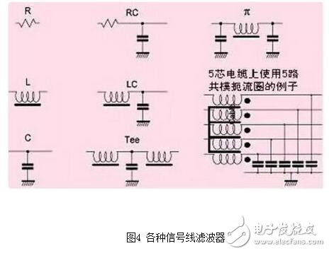
The basic working principle of the R and L filters is to generate a high impedance to reflect the interference, but this usually only achieves a few dB of attenuation. This filter is most suitable when both source and load impedance are low. The L filter can generate resonance, so it is preferably made of a soft ferrite magnetic material (see the following section). Since there is a parasitic bypass capacitance of about 0.2 pF in the resistor, the R filter loses filtering performance at high frequencies.
The C filter can generate a low impedance to reflect the interference, usually used in situations where the source and load impedance are relatively high. In general, the performance curve of the C filter seems to be ideal, but in reality it is far from this.
An RC filter with a larger R value is desirable because it does not produce significant resonance. However, when the signal frequency is above several kHz, or in a circuit with a transmission rate above kB/s, a high R value (preferably about 10k) is not suitable.
LC, T, and π-type filters can have higher attenuation values, but resonance occurs when they are connected to a non-50 source and load impedance environment. This problem can be solved by loading ferrite into the inductor. Ferrites exhibit inductive properties at low frequencies (sometimes up to about 10 MHz), but at higher frequencies they lose their inductive properties and exhibit resistive properties. The ferrite bead has an effective impedance of more than 1k at 100MHz, but the impedance at DC is less than 0.5, thus exhibiting a high-impedance state at the unwanted frequency and a low-resistance state at the useful frequency. A wide range of SMD ferrite beads are now available to meet a variety of spectrum needs.
A little-known feature of RF filters is that when it is not connected to a good RF reference ground, the effect is poor. The only ground reference, solid metal, or metal casing ("Faraday cage") on the PCB can be used as the RF reference ground. Ideally, at the highest frequency being filtered, they should not be greater than 1/100 of the wavelength. Holes (3mm at 1GHz in air or 1.5mm at 1GHz in FR4 fiberglass panels).
The connection between the capacitor and the RF ground in the filter should also be less than 1/100 of the wavelength, while also ensuring that the inductance is low. This means that a safe green/yellow wire cannot be used as a filter ground unless at very low frequencies. For example, if a power line filter with a 2.2nF Y-type capacitor is grounded through a 10cm long green/yellow wire, the Y-type capacitor will fail due to ground wire inductance at frequencies above 20MHz. .
When estimating the lap performance of the green/yellow wire ground, it can be assumed that the wire has an inductance value of about 1 nH/mm. The only correct connection of the filter is to connect the filter housing directly to the RF ground reference plane or housing. Of course, as long as there is a direct RF ground connection, it is not necessary to install a green/yellow wire for safety reasons.
If the filter is to be mounted on a PCB, its capacitance must be connected directly to the ground plane. If there is no ground plane, installing a filter with a capacitor is a waste of work. If the filter is mounted on a metal plate or shielded housing, it must be electrically conductive. Sometimes it is even necessary to attach a ring of conductive pad to the filter mounting surface to allow the filter housing to overlap the metal. A seamless RF bond is formed between the faces.
Military signal filters are generally of the C and π types because most common military equipment has a rugged, well-designed RF ground (metal cast chassis). Therefore, the filters used in this case are generally not affected by radio frequency defects.
However, for civilian, commercial and industrial products, the integrity of the radio frequency is often a serious problem because of the cost of the product. Therefore, I found that in this case, the better performance signal line filter is generally RC, LC or T type, connecting the resistor or inductor to the external conductor. This will make the RF current on the RF reference ground much smaller than the RF current generated by the C or π-type filter.
If a cable has multiple bundles of cores, it is usually best to pass all of the cores through a common mode choke. If it is important to reduce the crosstalk between sensitive signals, a common mode choke can be used for each signal in the core. Figure 5 shows an example of a five-way common mode choke for a five-core cable. The surface-mounted common mode choke can reach as many as eight in a square body of almost 5 mm.
If the power line filter does not allow 900MHz harmonics from the digital circuit to leak into the power line, then the optimized fit of the filter and shield should be considered. These harmonics close to the microwave frequency will enhance the radiation emission of the product.
Another lesser known feature of RF filters is to treat the filter and the shield as a whole, and the two complement each other. Incorrect filter structure design or installation methods can easily cause the product to emit radiation that exceeds the standard.
5. Filter structure and installationIf you want to achieve excellent filtering performance at high frequencies, the filter can easily degrade its performance due to RF leakage from its PCB traces and/or filtered and unfiltered interfaces. Many engineers and technicians are puzzled by RF leakage around the filter. Filtered and unfiltered traces and wires must be as far apart as possible from each other, and no other traces or wires pass through nearby filtered/unfiltered boundary lines. It is necessary to use shielding technology for the residual leakage of the filter that is not filtered.
If the external cable is filtered into a PCB board with a ground plane or an industrial instrument panel used as a radio frequency ground, the filter should be installed where the cable enters and exits the PCB board or instrument panel and is connected directly to the RF ground.
If the external cable is filtered and enters the shielded cabinet, the filter should be installed on the wall of the cabinet and electrically connected to the cabinet wall around the mounting hole. Isolated filters are the best choice (for example, feedthrough capacitors), but are generally more expensive and difficult to install.
Some types of filter connectors are also available on the market, such as D-type connectors (usually only 1nF capacitors, but magnetic beads, T and π filters are also effective).
For power line filters (usually for frequencies from 0 to 400 Hz with essentially the same performance), panel mounted filters typically use IEC sockets. Install the filter with the IEC socket on the metal casing on the shield. If there is no gap on the filter casing and electrically connect it to the shield metal piece as shown in Figure 6, it can be in the tens of Better performance in the frequency range of megahertz. Some manufacturers only pursue the normal operation of the filter in the range of the conducted emission test frequency (up to 30MHz). The cost of this filter is low, but the shielding integrity of the filter is affected, so that the product cannot pass the electromagnetic compatibility. Radiation emission test in the standard.
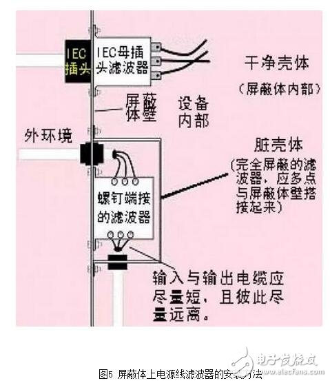
In high-power applications, most power line filters use screw connections, making it impossible to install the isolation board. Figure 5 shows that the dowel-mounted filter uses a "dirty box" method while encapsulating it in a shielded "dirty box" with an outer shield box. Even if the input and output cables in the dirty box are short and away from each other, the high frequency can still leak out, so it is necessary to set a magnetic ring for one cable or all cables to solve.
The overall feeling of the individual is summarized as follows:1. If the filter is not tested after the EMI and EMS indicators of the instrument, it is basically the main child of “Blind riding a horse, night half deep poolâ€;
2. If the machine selects a general-purpose filter that is commercially available, this filter can basically not be added;
3, the filter 8 points custom, 2 points universal is more reliable.
The reason for this conclusion is that because of several things that have been encountered recently, filters have been added, but the conduction is nothing. Finally, a filter sample is designed according to the test results. The ok is a pass, but the design itself. It is not complicated, but it adds one more differential mode capacitor and differential mode inductor, or adjusts the parameters of the filter inductor and capacitor. The general-purpose IEC socket filter has a small space inside. Generally, only two common mode capacitors, one differential mode capacitor and one common mode inductor can be placed. This thing can be put to the forefront. Mo Dawei.
How should the filter be selected?The first type is pre-aware (at least estimated) the frequency or frequency and intensity of the clutter to be filtered out, and then the attenuation requirement of the filter band is proposed. This requirement is given to the manufacturer, and a suitable filter is designed by the manufacturer. Device.
The second is to design the product first, and the position of the filter is reserved in the structure space. After the product is installed, the test is performed, and the filtering frequency and attenuation characteristics of the filter are determined according to the test result.
In addition to these two, there is basically no other way to effectively select the filter.
Onlyrelx Bar2000 dual flavor is portable and fashion disposable electronic cigarette, disposable ecigs pen are trending featured vape pen for vapors as it's safety and easy to use. Disposable vape pod,disposable vape, wholesale vape,vape wholesale,vape pen manufacturer and supplier.disposable vape pen,disposable electronic cigarette,disposable ecigs pen,disposable ecigs stick,disposable e-cigs pen,disposable vape factory,disposable vape pod,disposable vape device,vape pen,vape stick, vape wholesale,wholesale vape,customized dispsoable vape pen,customized vape pen,OEM&ODM disposable ecigs pen,disposable electronic cigarette wholesale, wholesale disposable electronic cigarette,distribute vape pen,vape pen distribute,high quality vape pen,high quality vape pod,rechargeable disposable vape pen,refillable vape pen,refilling electronic cigarette,rechargeable disposable electronic cigarette,refillable vape pod,disposable refillable ecigs,disposable refilling e-cigs pen,refillable e-cigs pen
Onlyrelx Bar2000 Dual Flavor,Disposable Vape Pen E-Cigarette,Disposable Vaporizer E-Cigarette,Best Electronic Cigarette Vape Pen
Shenzhen Onlyrelx Technology Co.,Ltd , https://www.onlyrelxtech.com