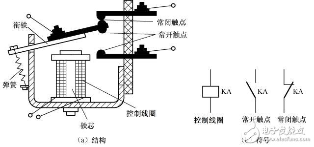
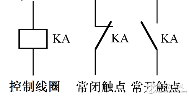
Relay, also known as electric cymbal, is an electronic control device that has a control system (also known as an input circuit) and a controlled system (also known as an output circuit). It is usually used in automatic control circuits. It is actually An "automatic switch" that uses a smaller current to control a larger current. Therefore, it plays the role of automatic adjustment, safety protection and conversion circuit in the circuit. The relay coil is indicated by a long square symbol in the circuit. If the relay has two coils, draw two long square boxes. At the same time, the relay's text symbol "J" is marked in the long box or next to the long box. There are two ways to represent the contacts of a relay: one is to draw them directly on the long square side, which is more intuitive.
There are many classification methods for relays. Today we introduce several common relays according to its working principle or structural characteristics.
thermal relay
A thermal relay operates by generating heat when a current passes through a heating element. Thermal relays are mainly used for thermal protection of electrical equipment, such as motor overload protection.
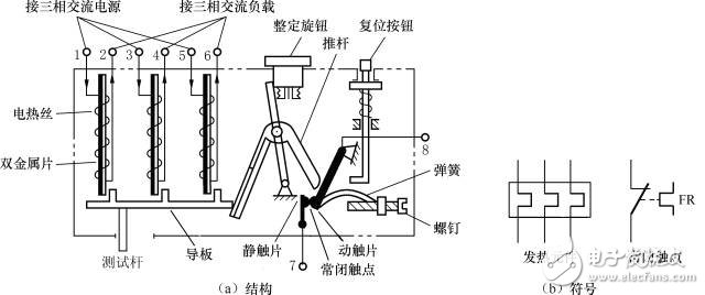
The thermal relay consists of a heating wire, a bimetal, a guide, a test rod, a push rod, a moving contact piece, a static contact piece, a spring, a screw, a reset button, and a setting knob. Only when the current flowing through the heating element exceeds a certain value (the rated current value of the heating element), the internal mechanism will act to make the normally closed contact open (or the normally open contact is closed), and the larger the current, the shorter the operating time. The rated current of the heating element of the thermal relay can be adjusted by setting the knob.
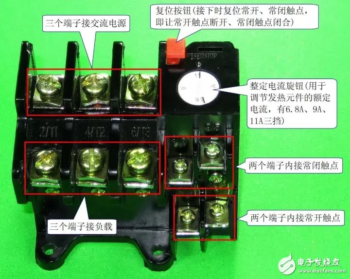
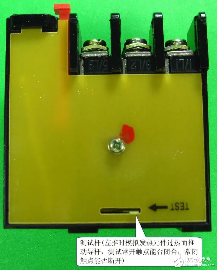
1. Shape and terminal
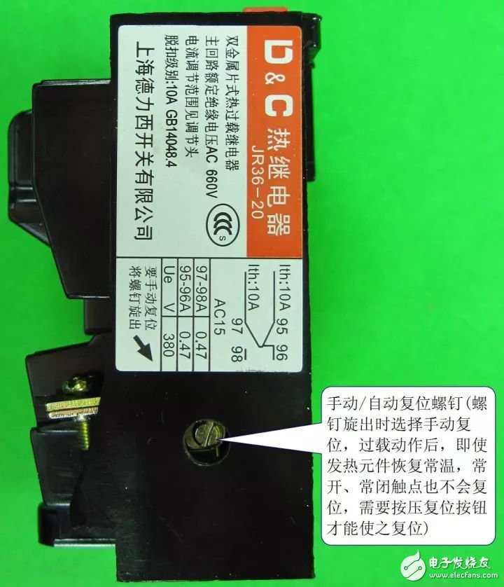
2. Reading of nameplate parameters

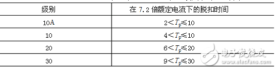
Trip level and time for thermal, electromagnetic and solid state relays
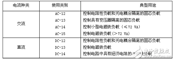
Type of use of electrical switching elements of control circuits
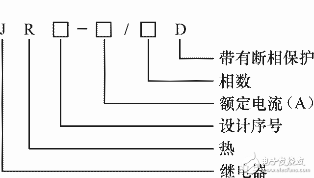
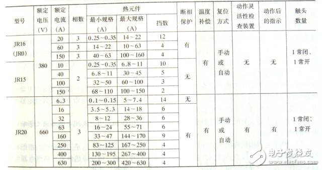
3. Model and parameters
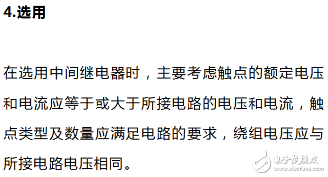
4. Selection
When the thermal relay is selected, the following principles can be followed:
1 In most cases, a two-phase thermal relay can be used (for three-phase voltages, the thermal relay can only connect two of them). For three-phase motors with three-phase voltage balance, unattended three-phase motors, or three-phase motors that share a set of fuses with large-capacity motors, three-phase thermal relays should be used.
2 The rated current of the thermal relay should be greater than the rated current of the load (usually the motor).
3 The rated current of the heating element of the thermal relay should be slightly larger than the rated current of the load.
4 The setting current of the thermal relay is generally equal to the rated current of the motor. For a motor that is easily damaged by overload, the setting current can be adjusted to be smaller, which is 60% to 80% of the rated current of the motor; for a motor with a long starting time or with an impact load, the setting current of the connected thermal relay can be slightly larger than that of the motor. The rated current is 1.1 to 1.15 times.
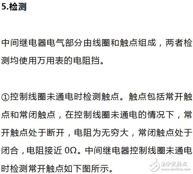
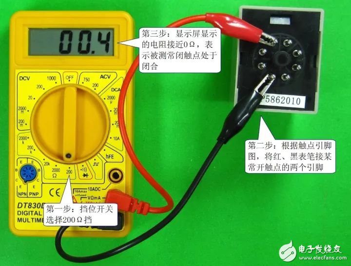
5. Detection
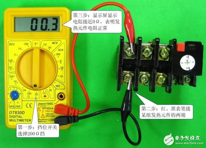
1) Detection of heating elements
The heating element consists of a heating wire or a heating sheet, and its resistance is small (close to 0 Ω). The heating element detection of the thermal relay is as shown in the figure below. The normal resistance of the three heating elements should be close to 0Ω. If the resistance is infinite (the digital multimeter displays the range symbol “1†or “OLâ€), the heating element is open.
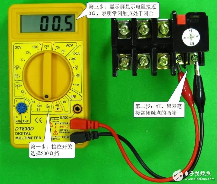
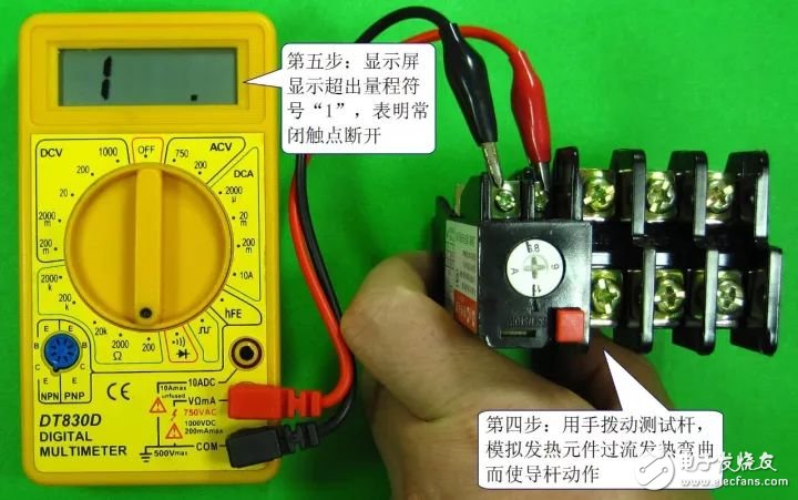
2) Detection contact
Thermal relays typically have a normally closed contact and a normally open contact. Contact detection includes detection during inactivity and detection during operation. Detecting the resistance of the normally closed contact of the thermal relay is shown in the figure below. The first picture shows the normally closed contact resistance when the sensor is not operating. It should be close to 0Ω normally, and then the normally closed contact resistance during the detection action. The test pole, as shown in the second figure, simulates the overheating of the heating element to bend the contact, the normally closed contact strain is open, and the resistance is infinite.
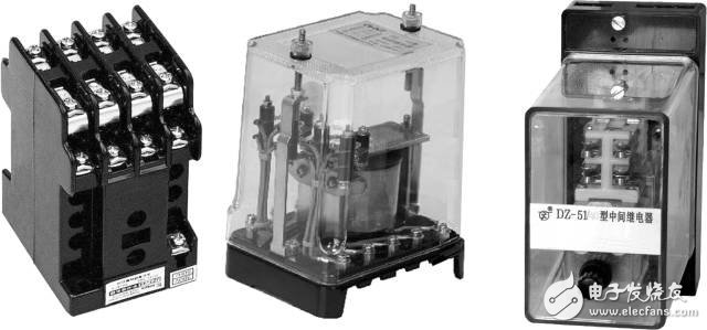
Intermediate relay
Current relays, voltage relays, and intermediate relays are all electromagnetic relays.
The intermediate relay is actually a voltage relay. The difference from the ordinary voltage relay is that the intermediate relay has many contacts, and the contact allows a large current to flow, and can open and close a circuit with a large current.
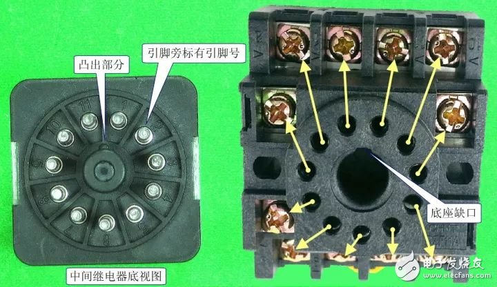
1. Symbol and physical shape
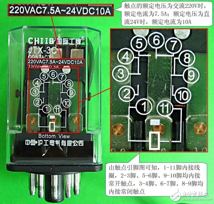
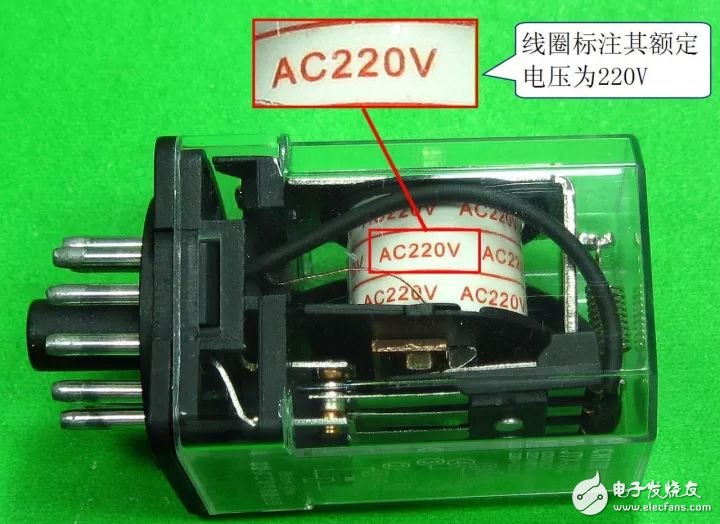
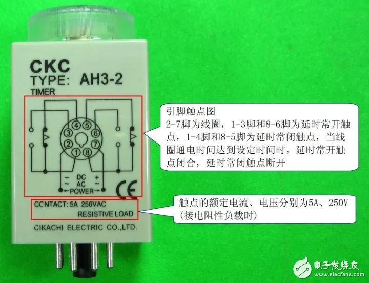
2. Pin contact diagram and reading of important parameters
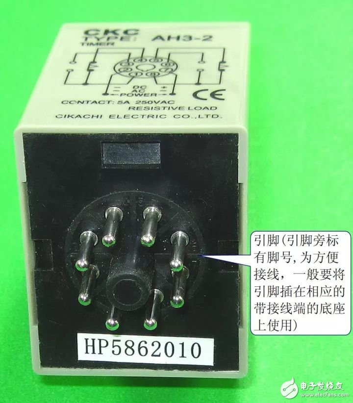
Intermediate relays with in-line pins are required for use in connection with the corresponding base for easy wiring installation.
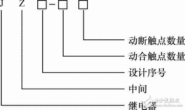
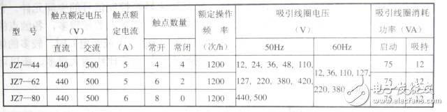
3. Model and parameters

1. Shapes and symbols
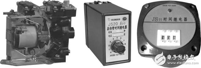
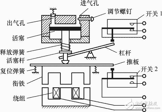
Structure of air damped time relay
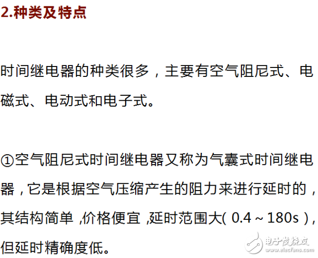
2 electromagnetic time relay delay time is short (0.3 ~ 1.6s), but its structure is relatively simple, usually used in power-off delay occasions and DC circuits.
3 The principle of the electric time relay is similar to that of the timepiece. It is delayed by the internal motor driving the reduction gear to rotate. This kind of relay has high delay precision and wide delay range (0.4~72h), but the structure is more complicated and the price is very expensive.
4 electronic time relay, also known as electronic time relay, it uses the delay circuit to delay. This type of relay has high precision and small size.
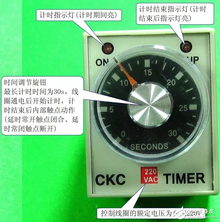
A commonly used power-on delay type electronic time relay
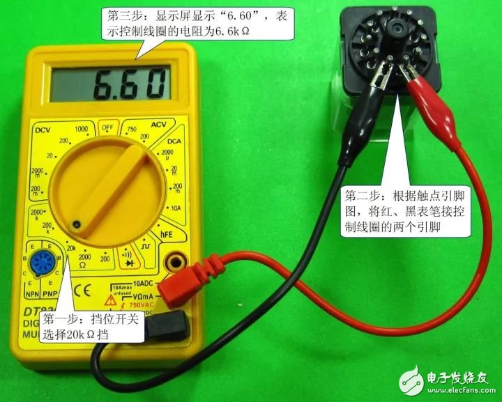
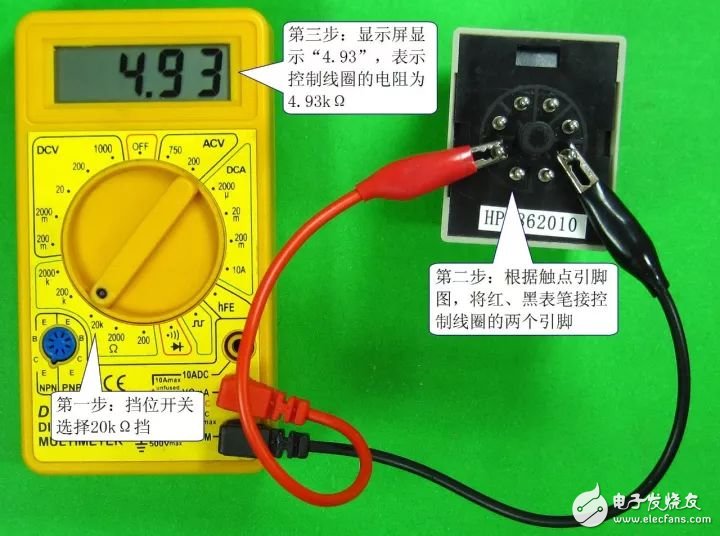
2 control coil detection. The detection of the time relay control coil is shown in the figure below.
There are a few different types of slip rings, but the most common type is called a cap slip ring. Cap slip rings have a cylindrical housing with an internal flange that fits over the end of the shaft. They typically have 6 or 12 channels and are available in a wide range of sizes.
Cap slip rings are used to provide electrical power and signals to and from rotating equipment. The channels on the slip ring allow for the passage of current and/or data signals through the ring. This allows for the rotation of devices such as antennae, radar dishes, and wind turbines without having to interrupt or disconnect the power or signal lines.
Cap slip rings are very reliable and can handle high speeds and heavy loads. They are also easy to install and maintain.
In the modern world, companies are always looking for ways to improve the efficiency of their machines and operations. Oubaibo offers a variety of products that can help improve your machine's performance. Their Cap Slip Ring allows for high-speed rotary unions, while their high-pressure swivel joints can handle even the most strenuous industrial applications. With so many options available, there's sure to be an Oubaibo product that can improve your machine's performance.
Cap Slip Ring,High Speed Rotary Unions,High Pressure Swivel Joints,High Pressure Swivel Joint
Dongguan Oubaibo Technology Co., Ltd. , https://www.sliprob.com