The DC motor has a wide speed range and smooth stepless speed regulation. The duty cycle of the PWM pulse signal is used to determine the average voltage output to the DC motor. By adjusting the duty cycle, the purpose of adjusting the output voltage can be achieved, and the output voltage can be continuously adjusted steplessly. Based on AT89S51 single-chip microcomputer, this paper proposes a design scheme based on DC motor speed regulation and speed measurement system, and then gives the main circuit structure of the system, as well as the design of drive circuit and system software. This program makes full use of the advantages of the single-chip microcomputer, and has the characteristics of high frequency and fast response. DC motors are commonly used in industrial production, with good starting and braking performance. Early DC motor control was based on analog circuits, using operational amplifiers, nonlinear integrated circuits, and a small number of digital circuits. The hardware part of the control system is complex, single-function, and difficult to debug. This solution uses a single-chip control system, so that many control functions and algorithms can be completed by software technology, which provides greater flexibility for the control of the DC motor and enables the system to achieve higher performance.
Main circuit design of speed regulation and speed measurement system
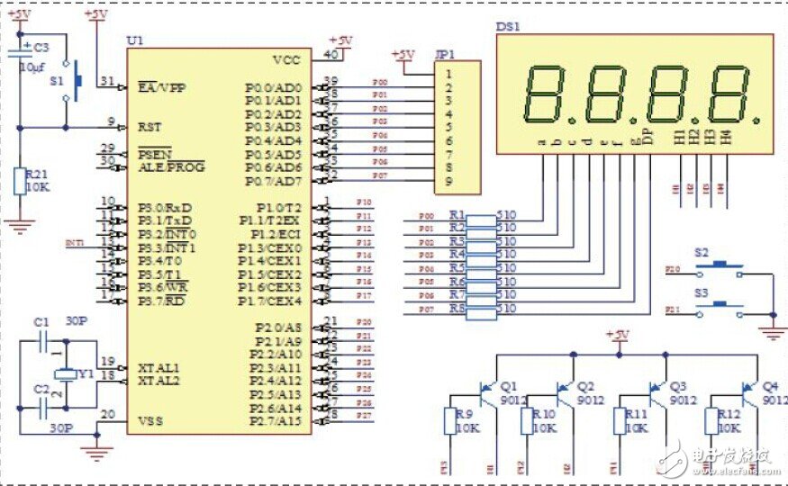
The whole system consists of input circuit, PWM modulation, speed measurement circuit, drive circuit, control part and display. The PWM modulation uses AT89S51 single-chip microcomputer to realize the frequency and duty cycle adjustment through software. The driving circuit is separated by an optocoupler protection circuit. The control part is composed of a single chip microcomputer and a peripheral circuit to realize various control requirements. The peripheral circuit mainly completes the acquisition, operation and speed control of the input signal, and the display part adopts a four-digit common digital tube. .

The hardware side is based on STC89C51 single-chip microcomputer, and the minimum system is composed with reset circuit, crystal oscillator circuit, drive circuit, speed measuring circuit, keyboard and LED display module. The software generates data output of the PWM pulse signal, keyboard, and LED display by programming in C51 language. The speed gear setting value is adjusted by the keyboard to realize tracking according to the set value, display on the LED display, and finally the PWM pulse signal is output by the single chip microcomputer, and the speed is fed back to the CPU through the speed measuring circuit and the speed is displayed on the LED display through the CPU. In order to reach the desired speed.
DC motor drive circuit design

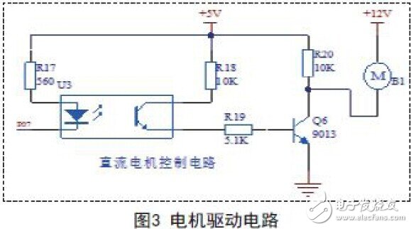
The control signal directly output from the single-chip microcomputer cannot directly drive the 12V DC motor. At present, most of the H-bridge drive is used. For the convenience of production, the drive module uses a photocoupler to isolate the control circuit from the main circuit to achieve protection. The U3 output PWM control signal drives the motor through the triode inversion to achieve motor speed regulation. The drive circuit diagram is shown in Figure 3.
Speed ​​measuring circuit design
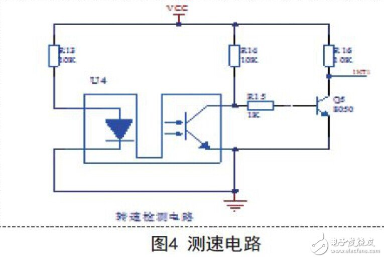
The speed measuring module is composed of a U-shaped photoelectric switch, a turntable and a peripheral circuit. When the motor rotates, the turntable is rotated, and eight small holes are attached to the turntable. When the turntable rotates one turn, eight pulse signals are generated, thereby converting the physical quantity of the motor rotation into The changed pulse signal is sent to the external interrupt P3.3 of the MCU for counting by the Q5 switch drive to realize the monitoring of the motor speed. The speed measuring circuit is shown in Figure 4.

A relatively common photoelectric speed measurement method is applied in the design, which is to fix a disc on the motor shaft and a U-type optocoupler in the speed measuring module. A pulse signal is generated through eight circular holes in the turntable. When the motor is turned to the hole, the light-emitting diode illuminates the phototransistor through the slit, and the triode is turned on, and the triode is turned off. The U-type photoelectric switch and the turntable are installed as shown in Figure 5: Fix the turntable on the rotating shaft of the motor, install the U-shaped optocoupler, insert the optocoupler into the turntable, fix it with screws, and install the U-shaped photoelectric switch on the side of the turntable. In the middle of the slot.
The design scheme of the speed measurement and speed regulation system based on the single-chip microcomputer control DC motor is to convert the input signal through the single-chip microcomputer and output the control signal to adjust the rotation speed of the DC motor through the drive circuit, and can monitor the speed of the DC motor in real time. High-precision speed control is achieved thanks to the PWM control technology. The speed measurement adopts photoelectric switch to easily realize the speed detection. For this reason, the speed measurement and speed control system of the DC motor designed in the scheme has the main circuits of speed input, detection, display, pulse width modulation and motor drive, which is convenient for the motor speed. Control and display.
tsvape , https://www.tsvaping.com