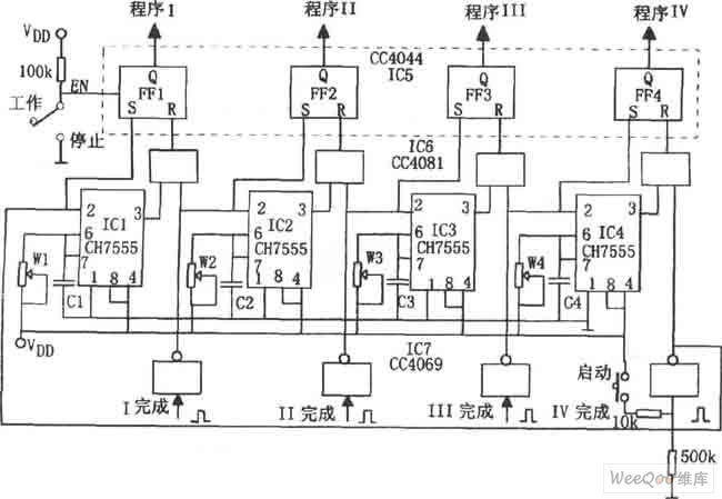
As shown in the figure is the program control circuit. The controller is composed of a loop program stable time circuit, a power-on trigger circuit and the like. The four 555 circuits IC1 to IC4 respectively constitute monostable circuits with different timings, and are connected in series with loop triggering. The power-on trigger circuit consists of an IC7 (CD4069) six-inverter, which sets the timing of each single-stable circuit. IC6 (CC4081) is a quad 2 input AND gate; IC5 (CC4044) is a quad R. S latch. When the start button is pressed, IC1 is set to enter the monostable transient state. That is, the first program runs. When the temporary stabilization ends, that is, the first program operation ends, the FF1 (RS flip-flop) is reset by the AND circuit, and the program II and the flip-flop IC2 are simultaneously started, and the loop is performed to perform program control. The timing of each program is determined by the time constant td = 1.1 RwC of that stage.

Nantong Double Star Automation Equipment Co., Ltd. , https://www.nt-doublestar.com