0 Preface
This article refers to the address: http://
Based on the existing electric vehicle power control method, this paper designs and implements a model electric vehicle motion control system combining electric power steering with double rear wheel independent driving. The system combines electric power steering with double rear wheel hub motor drive, omitting the traditional clutch, transmission, final drive and differential components, greatly simplifying the vehicle structure and greatly improving the electrification and controllability of electric vehicles. The full advantage of the high motor integration of electric vehicles has been brought into full play. The design and control methods of each key subsystem of the system are given in detail, and the effectiveness of the design is proved by bench experiments.
1 Model electric vehicle system overall composition
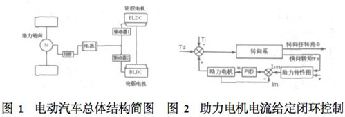
Designed for low-speed driving in the ideal condition of an electric vehicle (EV), a double rear wheel independent drive motion model is realized. The system structure is shown in Figure 1.
The model front wheel control uses an electric power steering (EPS) system, and the power is provided by two rear wheel motors. The electric power steering drive uses a common DC servo motor for simple control; the two rear wheel motors are two hub-type DC brushless (BLDC) motors that improve efficiency while ensuring long-term operational reliability. Each motor and electronic control unit (ECU) in the system form a speed closed loop and current closed loop system. This design can eliminate the clutch, transmission and final reducer of the traditional vehicle on the basis of maintaining the traditional driving feel of the vehicle. Parts such as the differential greatly simplify the structure of the vehicle, improve the transmission efficiency, and realize the power steering function through the control technology and the electronic differential control of the electric wheel.
2 Design of double rear wheel drive electric vehicle motion control system
The prototype electric vehicle motion control mainly needs to solve the following two problems: one is the power steering system control problem; the other is the coordinated control problem of two independent driving wheels.
2. 1 power steering control
The electric power steering work process is as follows: First, the torque sensor measures the steering torque applied by the driver on the steering wheel, the vehicle speed sensor measures the current running speed of the vehicle, and then transmits the two signals to the ECU; the ECU is based on the built-in control The strategy calculates the ideal target assist torque and converts it into a current command to the motor. Then, the assist torque generated by the motor is amplified by the speed reduction mechanism on the mechanical steering system, and the steering torque is overcome by the driver's steering torque to realize the vehicle. The turn.
The power-assisted motor control strategy uses closed-loop given control of the assisted motor current. The block diagram of its control function is shown in Figure 2.
Such a control structure simplifies the process of adjusting the actual assisting characteristics, and the control parameter adjustment is convenient and intuitive, and the economy is ensured on the basis of satisfying the control requirements.
2. 2 two drive wheel control
With the dual rear wheel independent drive scheme, each drive wheel can independently provide the driving force, and the power can be independently allocated as needed. The differential function can be completed by software to realize the electronic differential.
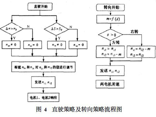
To determine whether the driver's driving intention is straight or steering, the steering wheel angle θ is an important parameter. In the strategy, the steering wheel free travel angle ε is introduced as a flag. When |θ| > ε, the vehicle electronic control unit (ECU) considers the driving intention to be steering, otherwise it is straight driving. Whether it is the direct drive control strategy or the steering control strategy, the key point is to control the motor on both sides by adjusting the target speeds ni1 and ni2, so as to achieve the manipulation of the vehicle body travel trajectory. The block diagram of the two-motor coordinated control is shown in Figure 3. 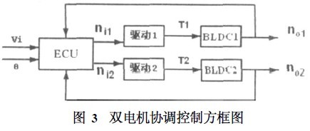
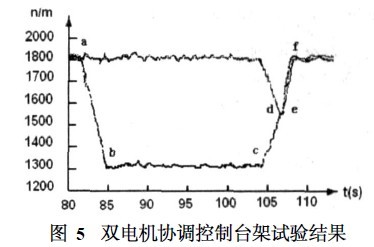
1) Direct driving control strategy In the straight running, the motor speeds no1 and no2 on both sides are difficult to achieve complete consistency, there will always be a certain speed difference △n (definition △n = no1 - no2), the ECU needs to △n For monitoring, when Δn exceeds the real-time speed difference np allowed by the system, it is necessary to adjust the target speeds ni1 and ni2 according to Δn and np, and the adjustment amount is nin; in order to ensure the stability of straight running, the ECU needs to The accumulated travel difference ΔS of the motor on both sides is monitored. When ΔS exceeds the real-time speed Sp allowed by the system, it is necessary to adjust the target rotational speeds ni1 and ni2 according to ΔS and Sp, and the adjustment amount is nis. Calculate nis, nis = C3 △S, C-proportional constant according to the accumulated stroke difference. According to the test, it should not be too large or it may cause instability. The calculation result is used to adjust the input speed of the two motors to reduce the accumulated stroke difference. Closed-loop control. Through the double synchronization of the accumulated stroke and speed, the reliability of the stable straight running of the vehicle is enhanced.
2) When the steering control strategy is steering control, the ECU calculates the target rotational speed difference m of the motor on both sides according to the absolute value of the steering wheel angle θ. According to the positive and negative of θ, it is determined which two motors in the drive system are the outer motor and who is the inner side. The target speed of the motor and the outer motor keeps the current speed constant, while the target speed of the inner motor should be adjusted up and down by m on the basis of the current target speed to achieve steering. Figure 4 is a control flow chart for straight driving and steering.
3 Experimental results
According to the above control strategy, the control program of the vehicle control electronic control unit (ECU) was compiled and tested. The experimental results are shown in Figure 5. It can be roughly divided into the following stages:
1) Before the point a, the vehicle travels straight.
2) Between points a and b, the driver quickly turns the steering wheel to the left to a larger angle Θ, then keeps the steering wheel position unchanged, and the vehicle begins to turn to the left. The motor 1 speed n1 remains unchanged, and the motor 2 speed n2 is adjusted downward until the target speed difference is reached.
3) Between b and c, the position of the steering wheel remains unchanged in the previous stage, and the motor 1 and motor 2 maintain a stable speed difference and the vehicle performs steering.
4) Between c and e points, the steering wheel returns to the middle position, the driver intends to drive straight. At this time, the motor 1 speed n1 is adjusted downward, the motor 2 speed n2 is modulated upward, and the two meet at point d; after the de section adjustment After reaching the basic point at point E.
5) There is an acceleration process between the e and f points, so that the speed of the vehicle reaches the speed before the steering.
6) After point f, the vehicle keeps running straight.
The experimental results show that the vehicle electronic control unit (ECU) can better control the motor on both sides through the coordinated control strategy based on angle and speed, and realize the driver's straight running and steering requirements in time.
4 Conclusion
The electric vehicle motion control model combined with electric power steering and double rear wheel drive technology is designed and designed. The coordinated control strategy of double hub motor based on angle and speed control is proposed to provide stable driving problem for dual rear drive electric vehicles. The solution. The test results of the bench show that the control strategy can better meet the requirements of the vehicle's linear driving and steering driving control, and prove the effectiveness of the design.
Electric Vehicle Battery Supply
Lithium-Ion Batteries
Lithium-ion batteries are currently used in most portable consumer electronics such as cell phones and laptops because of their high energy per unit mass relative to other electrical energy storage systems. They also have a high power-to-weight ratio, high energy efficiency, good high-temperature performance, and low self-discharge. Most components of lithium-ion batteries can be recycled, but the cost of material recovery remains a challenge for the industry. The U.S. Department of Energy is also supporting the Lithium-Ion Battery Recycling Prize to identify solutions for collecting, sorting, storing, and transporting spent and discarded lithium-ion batteries for eventual recycling and materials recovery. Most of today's PHEVs and EVs use lithium-ion batteries, though the exact chemistry often varies from that of consumer electronics batteries. Research and development are ongoing to reduce their relatively high cost, extend their useful life, and address safety concerns in regard to overheating.
Electric Vehicle Supply Chain,Electric Car Supply Chain,Supply Chain For Electric Vehicle Batteries,Materials For Ev Battery
Shenzhen Zhifu New Energy Co., Ltd. , https://www.sunbeambattery.com