Abstract: Vehicle transportation monitoring is the main content of open-pit mine vehicle management and one of the important factors affecting the production efficiency of open-pit mine enterprises. The development technology, system function and key technology of realizing GIS for open-pit mine vehicle transportation monitoring system are expounded. In the application of a molybdenum mine, the system is running well and real-time monitoring and dispatching of open-pit mine vehicles is realized.
Keywords: geographic information system; vehicle; monitoring; scheduling
This article refers to the address: http://
1 Introduction The open pit mine is a mining center. Large-scale production systems with transportation as the link, vehicle transportation plays an important role in open-pit mining enterprises. In large-scale open pit mining, infrastructure investment in mine transportation accounts for 40% to 60% of total investment, transportation costs account for 35% to 45% of total mine cost, and transportation energy consumption accounts for 40% to 70% of total mine energy consumption. . Therefore, vehicle transportation has become the focus of attention in the management of mining enterprises, and as the scale of production continues to expand, this part of the cost is also increasing.
GIS is an emerging discipline that integrates computer science, informatics, geography and many other sciences. With the support of computer software and hardware, the theory of systems engineering and information science is used to scientifically manage and comprehensively analyze geographic data with spatial connotations to provide spatial information systems for planning, management, decision-making and research. Applying GIS to open pit mines with a large amount of spatial information will greatly improve the safety of open-pit mine vehicles, effectively improve the vehicle's carrying rate and efficiency of ore distribution, effectively improve resource utilization, and develop mineral resources. Sustainable development is extremely significant.
2 Development technology The system is an applied geographic information system (GIS). Take Visual C#. Net as a development tool, integrated GIS functional component MapX, secondary development of "GIS-based open-pit mine vehicle transportation monitoring system." The storage of various geographic data and attribute data is implemented by the relational database management system sQLServer 2000.
3 System function GIS technology can provide a graphical human-machine interface in the vehicle transportation monitoring system, display the position of the vehicle in real time and accurately on the electronic map, track the driving process of the vehicle, and then realize the vehicle terminal query, path planning and most Excellent scheduling. The system mainly implements the following functions:
(1) The electronic map function realizes the functions of translation, enlargement, reduction, layer control, full image display, and center point selection of the electronic map in the visual interface of the system.
(2) Vehicle positioning monitoring includes vehicle monitoring settings, vehicle real-time monitoring, single target tracking, multi-target/area monitoring, vehicle attribute query and other functions.
(3) Historical trajectory management can select a detailed record of vehicle position information, police records and the like received by a certain vehicle stored in the database for a certain period of time to play back, and can control the playback process.
(4) The vehicle dispatcher mainly sends scheduling information, and can simultaneously transmit public information, company information, scheduling information, detailed Chinese or English information to a plurality of vehicle terminals.
(5) User login information management The user who logs in to the system records the login and logout time of the user in the background database, which facilitates attendance records and system operation management.
(6) Administrator information management administrator information and account management, through the advanced administrator can add or modify the management level of other administrators, and add administrator data.
(7) Vehicle information management Management vehicle related information, including company information, team information, vehicle information and driver information addition, modification, and deletion.
(8) The operation log management includes two aspects: one is the login information of the administrator saved for system security considerations: the other is the detailed record of the alarm, fault and moving target trajectory in the database, which is convenient for the user to query.
4 Key technologies for GIS implementation
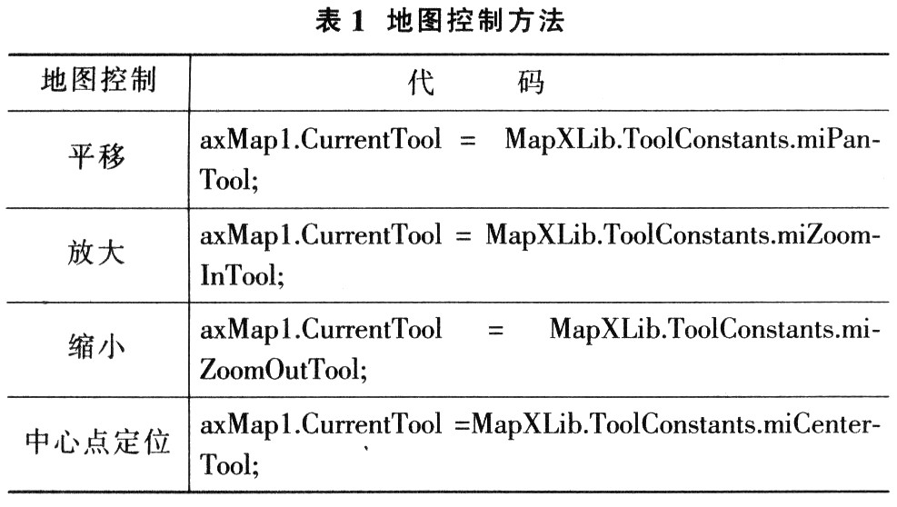
4.1 Map Control in Microsoft Visual Studio. Create a new Visual C# project in the NET 2003 environment, and select the template as a Windows application. After the MapX control is introduced in the program, the United States map in the MapX installation directory will be automatically loaded as the default map. You can load the map 161 in any gst format by changing the GeoSet property of the MapX control. The core source code for implementing GIS map control is shown in Table 1.
4.2 Accessing Data in a DBMS By binding to geographic data in a database, you can create a new layer on the map and display each latitude and longitude data as a point on the map. By using MapX's Datasets. The Add method can add a table in SQL Server as a data set, and also use the BindLayer object as a parameter of the method, so that the map and data can be bound.
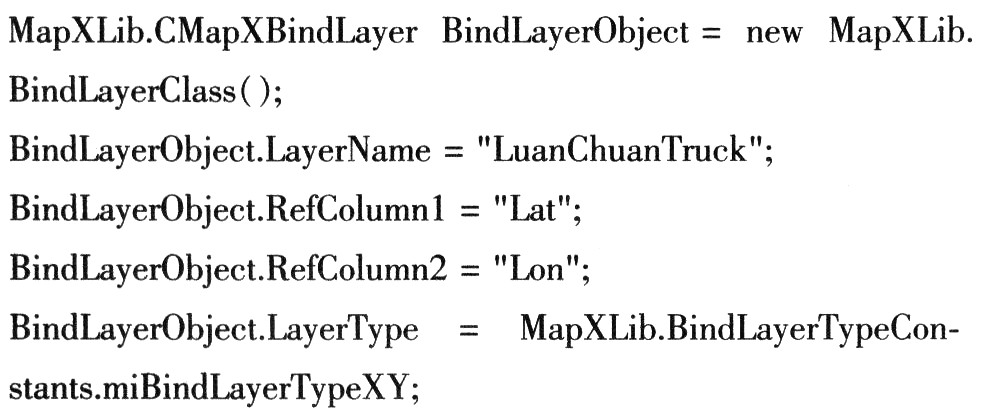
4.2.1 BindLayer Object Create a BindLayer object, BindLayerObject, to add a dataset to create a point at the location specified by the data on the new layer. The Lay-erName property of the BindLayer object specifies the name of the newly created layer. The RefColumnl attribute specifies the field containing the latitude, the RefColumn2 attribute specifies the field containing the longitude, and the LayerType attribute specifies the layer type to which the data is bound.
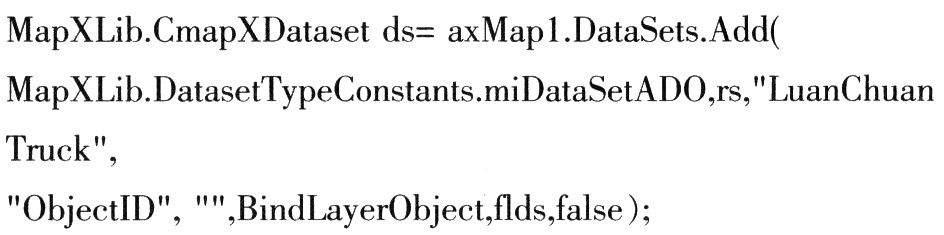
4.2.2 Datasets. Add method Use Datasets. The Add method specifies a specific data set and adds it to the Datasets collection, binding the data in the data source to MapX, and binding the data in the external data source to the map. Datasets. The syntax of the Add method is: Dataset-S. Add (Type, SourceData, Name, Geofield, Secondary-Geofield, BindLayer, Fields, Dynamic). The Type parameter is the added dataset type: SourceData parameter reference data: The Name parameter is a string that uniquely identifies the dataset: the Geofield parameter is the name or index of the column containing the geographic information in the data source; SecondaryGeofield is an optional parameter, only the dataset This parameter is required when the bound key contains a unique keyword column: the Bind-Layer parameter specifies the map layer to which the data will be connected; the Fields parameter describes the field to be imported in the data source; the Dynamic parameter Is a Boolean value that controls whether data binding is dynamic.
4.3 Graphs and mutual checks Use Point. Set method sets the coordinates of the vehicle to be displayed, using Layer. The SearchAtPoint method searches for the primitives at the coordinates. By matching the names of the primitives with the vehicle numbers in the database, the attribute data of the vehicles in the database can be bound to the map to realize the mutual inspection of the maps.

5 Application of open-pit mine vehicle transportation monitoring system The system is applied in a molybdenum mine, mainly for real-time monitoring and dispatching of open-pit mine production vehicles. The whole system consists of vehicle terminal, GSM/GPRS communication link, server middleware system and client software system. The overall structure of the system is shown in Figure 1.
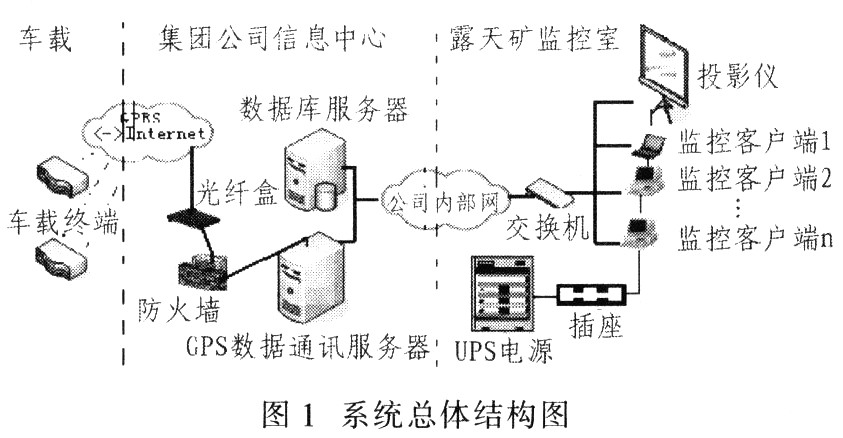
The vehicle terminal completes data collection and information transmission of vehicle positioning, vehicle status, GSM/GPRS communication link completes information interaction, vehicle monitoring center server completes vehicle data reception and data storage, and client software completes vehicle monitoring and scheduling. Features.
5.1 Vehicle terminal deployment The entire system has 95 vehicle terminals, and the vehicle terminals communicate with the data communication server via the GPRS network. The vehicle terminal is composed of a terminal host, a GPS antenna, a GPRS antenna, a host display screen, a signal indicator light, a headphone and a speaker device.
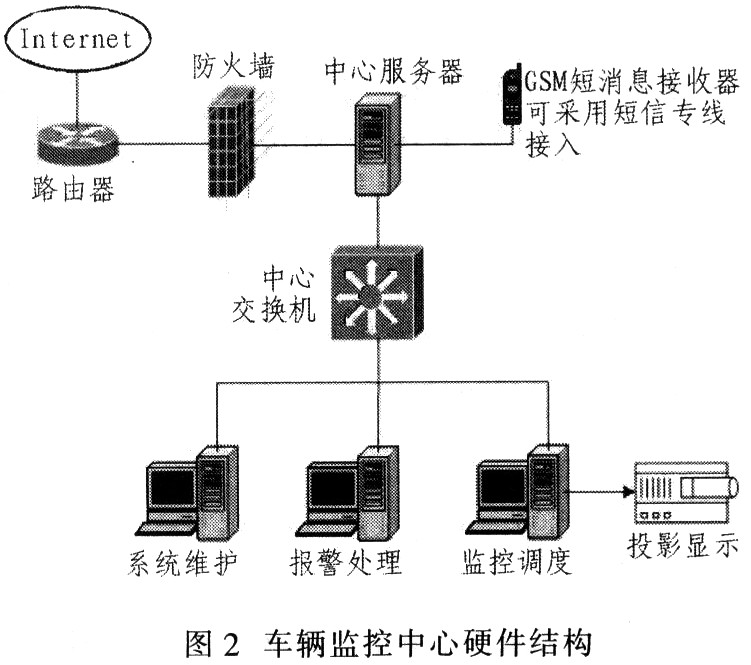
5.2 Vehicle Monitoring Center Deployment (1) Monitoring Center Hardware The vehicle monitoring center consists of two parts: 1 in the monitoring room of the open pit mine, there are two monitoring computers, one dispatching computer, one alarm processing computer, one daily Office computer and a large screen projector, responsible for vehicle monitoring and scheduling functions; 2 information management center, placed data communication server and database server, responsible for the completion of vehicle data reception and data storage. The two are more than 10 kilometers apart, and the system communicates through the internal network. The hardware structure of the monitoring center is shown in Figure 2.
(2) The design of the software structure software of the monitoring center adopts the client, server (Client/Server), ie C/S structure, to decompose a database application system into the front-end client monitoring application, the background database server and the data communication server. section. The core of this structure is that the client application only sends the service request, the server accepts the request, performs the corresponding operation, and returns the result of the operation to the client application.
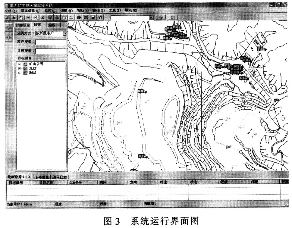
The monitoring client is responsible for running the vehicle transportation monitoring system, and visually presenting the position and running track of the vehicle in front of the user. The client application running interface is shown in FIG. 3 .
6 Conclusion Based on GIS technology, the open-pit mine vehicle transportation monitoring system is stable and reliable in the application of a molybdenum mine open pit mine, and achieves the intended purpose. The system realizes real-time dynamic tracking and monitoring of all vehicles on the GIS platform, and can issue corresponding instructions to each vehicle to control its operation according to production requirements, thereby ensuring orderly and efficient production. It can be foreseen that the use of GIS technology to plan and manage the information resources of mining enterprises has broad prospects for development.
REMOTE CONTROL SOCKET
Important Safeguards
When using any electrical appliance, in order to reduce the risk of fire, electric shock and/or injury to persons, basic safety precautions should always be follow8d. including:
• The appliance is for household and indoor use only.
• Before plugging in. check that the voitage on the rating label is the same as the mains supply.
• To protect against electric shock, do not immerse any part of the product in water or other liquid.
• This socket is intended for use by competent adults only and children should be supervised at all times.
• Do not use the socket for other than its intended use.
• This socket can be used by children aged from 8 years arxl above and persons with reduced physical, sensory or mental capabilities or lack of experience and knowledge if they have been given supervision or instruction concerning use of the appliance in a safe way and understand the hazards involved. Children shall not p<ay with the appliance Cleaning and user maintenance shall M be made by children without supervision.
• Children of less than 3 years should be kept away unless continuously supervised.
Children from 3 years and less than 8 years shall only switch on/off the appliance provided that it has been placed or installed in its intended normal operating position and they have been supervision or instruction concerning use of the appliance in a safe way and understand the hazards involved. Children aged from 3 years and less than 8 years shall not plug in. regulate and clean the appliance or perform user maintenance.
• Don't use this socket in the immediate surroundings of a bath, a shower or a swimming pool.
• In case of malfunction, do not try to repair the socket yourself, it may result in a fire hazard or electric shock
Do Not Exceed Maximum a680W
Place the LR44 batteries provided into the compartment in the back of the Remote Control, please insert as sho*/m in the back of the compartment to ensure the polarity is correct.
Programming Instructions
• Plug the Remoce Socket$($)lnto the wall socket(s) and switch on the mams supply, the red LED will flash every second.
• If the LED is not flashing press & hold the manual ON/OFF button for 5 seconds until it Hashes
•Press any ON switch on the Remote Control for approximately 2 seconds and the Remote Socket(s) learn the code. The LED will stop flashing top confirm the codehas been accepted.
• Any number of Remote Sockets can be programmed to one Remote Control ON button to create multiple switching.
• To programme o<her Remote Sockets on different Remote Control ON buttons repeat the prevous steps
• If the mains supply is turned off the Remote Sockets v/ill lose their code and it wil be necessary to re-pcogramme.
Operation:
• Plug your appliance(s) into the Remote Socket(s)
• Press the programmed ON or OFF button on the Remote Control to control the Remote Socket.
♦ The Remote Sockets can also be operated manually using its ON/OFF Button Trouble shooting
If a Remote Socket does not react to the Remote Control please check the followng:
♦ Low battery in tbo Remote Control
• Distance too large between the remote control and the recerver (ensure the range distance is no more than 20 clear Metres) and free from obstacle that may reduce the distance.
• If programming has not been successful, tum the power off and back on then follow the programming steps above.
How to decode
• Press the manual ONX)FF button for 5 seconds until the red LED flashes once per
second to confirm de-coding is successful
♦ Press the ALL OFF switch on the Remote Control for more than 3 seconds, the LED
flashes once per second to confirm (decoding successful.
Voltage: 240V-/50HZ
Max power rating: 3680W max.
Remote frequency:
Remote range:
Battery Type:
433.92MHz
230 Metres
Button Cell 2x1.5V LR44 =
Please check with your local waste management service authority regarding regulations for the safe disposal of the batteries. The batteries should never be placed G municipal waste.
Use a battery d^posal facility if available
M
For eioctncal products sold within the European Community. At the end of the electrical products useful life, it should not be disposed of wth household waste. Please recycle faaMies exist. Check with your Local Authonty or retailer for recycling advice.
C€
remote socket,remote power socket,remote control plugs,remote plug socket
NINGBO COWELL ELECTRONICS & TECHNOLOGY CO., LTD , https://www.cowellsocket.com