A distinctive feature of modern civilization is the colorful advertisements that can be seen everywhere in the city, most of which are Chinese characters or graphic advertisements made by LED dot matrix, which are widely used in banks, hospitals, hotels, railway stations, stadiums and Other public place.
The traditional design method of Chinese character scrolling display is controlled by a single-chip microcomputer. Although the single-chip solution has the characteristics of low price and flexible programming, due to the limitation of the hardware resources of the single-chip microcomputer, future design changes and upgrades will always require more research and development. The cost of funding and a long time-to-market cycle may even need to be redesigned. Moreover, in a display-oriented system, the utilization rate of the main functions such as operation and control of the single-chip microcomputer is very low, and the advantages of the single-chip microcomputer cannot be used, which is equivalent to a great waste of resources.
Using the top-down modular design method of EDA technology, with the help of related development software, such as Qualtus II software, the hardware description language-VHDL program is solidified in the FPGA (on-site) with abundant I/O ports, internal logic and wiring resources. Programmable gate array). This technology has the advantages of high system design efficiency, good integration, strong confidentiality, easy modification, easy implementation, etc., and has become the mainstream technology of digital system design today. The LED dot matrix controller made in this way, because it is a pure hardware behavior, has significant advantages such as fast speed, high reliability, strong anti-interference ability, and short development cycle.
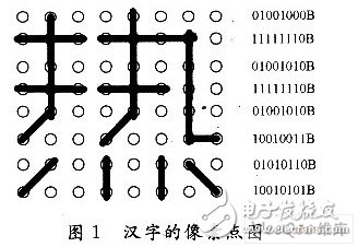
1 Principle of EDA dot matrix display of Chinese charactersTake the 8×8 LED dot matrix as an example. The 8×8 LED dot matrix is ​​made up of 64 light-emitting diodes arranged in a matrix. The light-emitting tubes in each row have a common anode (or cathode), and each column has a common anode (or cathode). The luminous tube has a common cathode (or anode), which generally displays Chinese characters or graphics in a dynamic scanning mode. Scanning is divided into three ways: point scanning, row scanning and column scanning. Row scanning needs to extract font codes by row, and column scanning needs to extract font codes by column. In order to meet the requirement of persistence of vision, if the point scan mode is used, the scan frequency must be greater than 16×64=1 024Hz, and the period must be less than 1ms. If row or column scanning is used, the frequency must be greater than 16×8=128Hz, and the period must be less than 7.8ms. Since the experiment board used is provided with a 1 kHz clock, the clock is used for scanning in the design of this example, so that the scanning time of each line is 1 ms, and the experimental results show that the brightness is appropriate. Now take line scan as an example to briefly explain the principle of dynamic scan display. Figure 1 shows the line pattern of the Chinese character "Heat" when the dot matrix is ​​a column of common yang. When working, first output the dot matrix font of the row to be scanned from each column, and then let the decoder select (scan) the row to display the row, and then send the next row of data, and then make the next row valid until all 8 rows Be scanned again. At this point, a complete text message is displayed, and then these 8 lines are scanned repeatedly until the new message is displayed. The following design uses line scanning to achieve scrolling display.
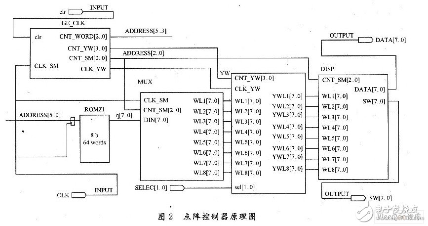
The whole circuit is composed of five parts: clock counting module GEL_CLK, ROM module ROMZI storing Chinese characters, data distributor module MUX, shift module YW and display module XIANSH-I. The clock counting module is used to generate the clock required by the entire circuit and its counter value to the clock, such as: shift clock CLK YW, shift counter CNT YW, word counter CNT WORD, display scan counter CNT SM. The ROMZI module is customized by LPM 1PORT ROM in Qualtusâ…¡, which is used to store 8 Chinese characters to be displayed. The MUX module is used to read the 8 line font information of a Chinese character from the ROM under the action of the scan clock and the scan counter, and send it to the shift module YW. The YW module is under the action of the shift clock and the shift counter, according to SELECT Signal selection performs corresponding shifts (left shift, right shift, up shift, down shift) on the read font information, and finally sends the display module DISP to drive the LED dot matrix to display Chinese characters. The schematic diagram is shown in Figure 2.
The clock count generation module is based on the input clock of 1 kHz, and carries on the 17-bit cycle count CNT[16. . O]. This clock is not only a clock for dynamic scan display, but also a clock that takes a word of 8 characters from the ROM, and a 3-bit cycle count is performed on it as a scanning display counter and a word code counter for taking one word. CNT[16. . CNT[9] in O] is the 1 024 frequency division of the clock, which is used as the shift clock CNT_YW with a period of about ls. As a 4-bit shift counter, CNT[13...lO] counts the shift clock CLK_YW and counts the number of shift bits. The 16 states make a Chinese character move into the dot matrix column by column, and then move out column by column. After every 16 shift clocks, one Chinese character will be displayed. CNT[16. . 14] As a 3-bit word fetch counter.
CNT[16…14]&CNT[2. . O] as a ROM address generator.
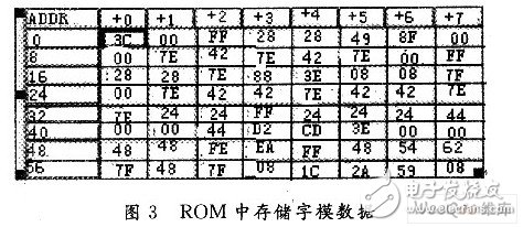
3.2 ROMZI moduleUse the single-port ROM in the LPM parameterized module library and customize it with the MegaWizard Plug-In Manager in Qualtusâ…¡. Before customization, you must first make the LPM ROM initialization file, which stores the font data of the Chinese characters to be displayed, and then follow the LPM MegaWizardPlug-In Manager The wizard prompts to customize according to the design requirements.
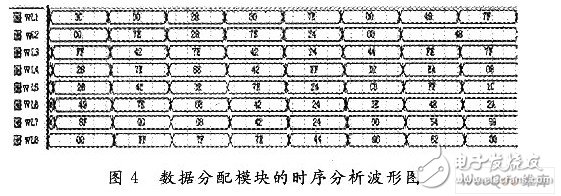
Figure 3 shows the font code of the initial Chinese character "Happy New Year's Day and Happy Birthday" in the customized ROM. The data distribution module MUX requires that under the action of 8 clocks, one line (8 font codes of a Chinese character) can be read from the ROM and sent to the output terminals of WL1-WL8 in the data distributor respectively. Figure 4 shows the font data read by the data distribution module under the scan clock. Comparing Figures 3 and 4 shows that the simulation results are correct and can meet the requirements of the problem.
The shift module YW is the core of the whole design. The row scan realizes the left shift. It shifts the font of each row by one bit to the left through each shift clock. When the scan clock arrives, the shifted new font is sent out. Through 8 shifts, a Chinese character can be moved out of the dot matrix plane. According to a similar principle, a Chinese character can also be moved into the dot matrix plane after 8 shifts. In this example (Figure 2), CNT YW is the count value of the shift clock, WL1~WL8 are the original fonts of Chinese characters to be displayed, L10~L80 are the 8-row display font information sent from the column after shifting, LL1~ LL8 is a temporary storage signal of 8 original font information not sent out. In the design, 16 shift clocks are needed. The WLl~WL8 fonts are moved into the LED dot matrix plane through the first 8 clocks, and the Chinese characters are moved out one by one after the latter 8 clocks. For the design of the shift register in the shift design reference, the sub-count value is "0000" and the non-"0000" is processed in two parts. The processing of the first line of fonts is:
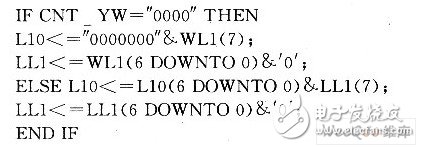
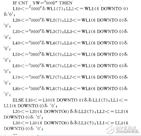
Other lines can be processed in the same way, please refer to the following procedures for details:
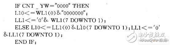
The right shift processing method is opposite to the above left shift, such as the first line can be processed as follows:
Part of the program when shifting upwards is compiled according to the following idea: when CNT_YW is the initial state "0000" for L10~L70, each signal is assigned X "00", when it is not the initial state, all move up one bit. Namely: L10
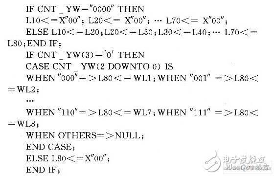
Moving down the program can be edited in the opposite way.
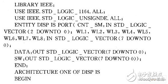
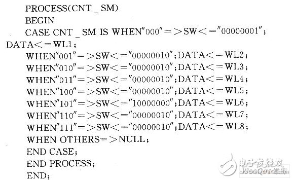
3.4 Display module DISP designThe display module DISP uses CNT_SM as the scan counter, which is a three-digit cycle count of 1kHz, which is generated by the aforementioned clock count generation module. WL1~WL8 are 8 8-bit font codes to be sent for display, and are determined by the aforementioned shift module. YW provides; SW[7. . O] is the line scan output signal, connected to the 8 lines of the dot matrix; DATA[7. . 0] is the corresponding column output font code during row scanning, which is externally connected to the 8 columns of the dot matrix. The dynamic display program of the digital tube in the reference of this module is designed as follows:
The above modules have passed the simulation verification in Qualtusâ…¡, and finally the hardware verification of the overall design. Load the design into the Cyclone series EPlC6Q-240C8 FPGA device of the KH31001 development board. The experiment proves that the scrolling display of Chinese characters is normal and the display can be shifted as expected. This shows. The core hardware of FPGA works well and can correctly realize the required design functions.
5 System expansionThis article is designed for 8×8 dot matrix, so 8 glyph codes are taken each time. If it is 16×16 dot matrix, change the glyph code stored in RONZI to 16 bits, and the data line to 16 bits. A Chinese character requires 16 A 16-bit font code, the data distribution module MUX, the shift module YW, and the display module DISP all need to change the original 8 bits in the input and output data to the corresponding 16 bits. The scan and fetch word code counter CNT_SM should be changed to the lower 4 bits of the CNT counter. A total of 32 states are required to move in and out of a 16×16 dot matrix Chinese character. Provided by a 5-bit counter. Such as using CNT[16. . The 14 to 10 bits in 0] are used as the counter, which can be modified in the clock counter generating unit CLK_GE. The word counter CNT WORD is counted by adding 1 for every 16 words taken. The decoder showing the DISP part should be changed from 3-8 decoding to 4-16 decoding. The more Chinese character information displayed, the more the number of ROM address lines, the word counter CNT_WORD should be in the clock counter generating unit GE_CLK, expand the corresponding counter number of bits, and the highest bit of the CNT counter to bit 15. If there are still 8 Chinese characters, the counter should be CNT[17. . O], CNT[17. . 15] is a word counter; if it is 16 Chinese characters, the counter should be CNT[18. . O], CNT[18. . 15] is the word counter, ..., and so on.
6 ConclusionThis paper implements the LED dot matrix Chinese character scrolling display based on Altera’s Cyclone I series FPGA device EPlC6Q240C8 hardware and VHDL hardware description language on the KH31001 development board, which can scroll and display "Happy New Year's Day and Happy Birthday" on an 8×8 dot matrix Chinese characters. Starting from the explanation of the principle of LED dot matrix display of Chinese characters, the paper presents the principle diagram of the dot matrix Chinese character scrolling display controller, the VHDL source program and timing simulation diagram of some modules, and the scroll mode can be selected by the button: left, right Move, move up, move down, etc., give the idea of ​​changing the system to expand to 16×16 dot matrix Chinese character scrolling. It can be seen from the system expansion scheme described in the article that when the number of characters displayed by the system changes, only the control logic and connection relationship need to be modified appropriately, and then the modified program can be downloaded to the device. Obviously, the maintenance of the system It is extremely convenient and easy to modify and modify. This article also has certain reference value for similar designs.
Portable radios,Motorola Two Way Radios,Motorola Talkabout Radios,Motorola Handheld Radio
Guangzhou Etmy Technology Co., Ltd. , https://www.gzdigitaltalkie.com