1 Introduction
This article refers to the address: http://
Modern industrial automation systems are moving towards intelligent, networked and open architecture. Realizing communication between different types of automation equipment is the key to system integration. The field control device has a communication function to facilitate the construction of the plant's underlying control network. The openness and consistency of communication standards make the system open and interoperable between devices. The normalization of function blocks and structures makes interchangeability between devices of the same function. The control function is placed on the site to make the control system structure highly dispersible. Using fieldbus technology to unify various smart devices that meet the same standard, completely realize the decentralized control of the entire monitoring system, which will improve system integration and data transmission efficiency, extend effective control distance, and improve system anti-interference performance and Expand system functionality. Serial communication based on Modbus protocol is one of the more common methods.
2 Introduction to MODBUS Protocol
The MODBUS protocol has the characteristics of strong debugging capability, large data transmission, and good real-time performance. It has become a very widely used communication language in the field of self-control. This paper introduces how to use the single-chip programming to realize the working process of online communication ModBUS message through an application example, and complete the allocation of address field, function code domain, data domain and CRC in visual language environment. The MODBUS protocol is a communication language applied to electronic controllers. Using this protocol, the controllers communicate with each other (eg, 485, 232C, etc.) and the controller communicates with other devices over a network (eg, Ethernet). It defines a message structure that the controller can recognize, regardless of the network implementation they are through; describes the process by which the controller requests access to other devices, how to respond to requests from other devices, and how to debug and log ; Develop a common format for message domain patterns and content. The MODBUS communication protocol is specified according to the master-slave device. For example, the master station can send a communication request (or command) to one or all the slave stations at a time, and the master device strobes the slave device through the address field of the message frame. The content and order of the message frame sent by the primary station are: slave address (device address), function code, data field (data start address, data amount, data content), CRC check code; information content of the slave response The sequence is basically the same as the master station information frame. In addition to defining the communication function code, MODBUS also defines an error code to mark the error message. After receiving the error code, the primary station takes corresponding measures according to the cause of the error. The data content of the slave response is responded to by the function code. For example, function code 03 requires reading the contents of the holding registers in the slave device.
2.1 MODBUS communication transmission mode
MODBUS communication implementation has two transmission modes (ASCII or RTU). ABB's 50 series PLC products use RTU (Remote Terminal Unit) mode. Each 8Bit byte in the message contains two 4Bit hexadecimals. character. The main advantage of this approach is that at the same baud rate, more data can be transferred than ASCII.
Code system:
· 8-bit binary, hexadecimal number 0...9, A...F.
· Each 8-bit field in the message is a bit of two hexadecimal characters that make up each byte.
· 1 start bit.
· 8 data bits, the smallest valid bit is sent first.
· 1 parity bit, no parity.
· 1 stop bit (with calibration) and 2 bits (without calibration).
· Error detection domain, CRC (Cyclic Redundancy Detection).
The RSTU-based RTU mode MODBUS communication format is:
It defines each bit of a message segment that is continuously transmitted over these networks, and decides how to package the information into a message domain and how to decode it.
2.2 MODBUS communication query response function
(1) Query The function code in the query message tells the selected slave device which function to perform. The data segment contains any additional information from the device to perform the function. For example, function code 03 is a requirement to read the holding registers from the device and return them. The data segment must contain information about the slave device to be told: from which register to start reading and the number of registers to read. The error detection domain provides a way for the slave to verify that the message content is correct.
(2) Response If the slave device generates a normal response, the function code in the response message is a response to the function code in the query message. The data segment includes data collected from the device: like register values ​​or status. If an error occurs, the function code will be modified to indicate that the response message is incorrect, and the data segment contains the code describing the error message. The error detection field allows the master device to confirm that the message content is available.
2.3 MODBUS message frame
The transmitting device converts the MODBUS message into a frame with a start and end point, which allows the receiving device to start working at the beginning of the message, read the address assignment information, determine which variable is selected, and determine when the message has been completed. Some messages can also detect errors and can be set to return results. With RTU mode, message transmission begins with a pause interval of at least 3.5 characters. The first field transmitted is the variable address. The transfer characters that can be used are hexadecimal 0...9, A...F. Network devices constantly detect the network bus, including the pause interval. When the first domain (address field) is received, each device decodes it to determine if it is sent to itself. After the last transmitted character, a pause of at least 3.5 characters calibrates the end of the message. A new message can start after this pause.
The entire message frame must be transmitted as a continuous stream. If there is a pause of more than 1.5 character time before the frame is completed, the receiving device will refresh the incomplete message and assume that the next byte is the address field of a new message. Similarly, if a new message begins with the previous message in less than 3.5 character times, the receiving device will consider it a continuation of the previous message. This will result in an error because the value of the last CRC field may not be correct. Therefore, when the communication port is initialized, the Timer1 timing interval is set to 500ms.
2.4 MODBUS CRC check principle
In the RTU mode in which the CRC check implements MODBUS communication, the last two bytes of the information frame are specified to pass a CRC (Cyclic Redundancy Check) code. The sender shifts all the bytes of the address field, function code and data field in the information frame in a prescribed manner and performs XOR (exclusive OR) calculation to obtain a 2-byte CRC code and includes the CRC check code. The information frame is transmitted as a continuous stream. The receiver performs the calculation in the same way when receiving the information frame, and compares the result with the double byte of the received CRC code. If it is consistent, the communication is considered correct, otherwise the communication is considered incorrect, and the slave will send a CRC error. answer. The RTU mode generally adopts the CRC-16 redundancy check method, and the check code of the CRC-16 is 16 bits (2 bytes), wherein the low byte is first and the high byte is after. There are two ways to implement the CRC check: calculate according to the definition formula of the CRC check, or establish a CRC check value table in the program. It is easier to implement the former in the program. Here you need to use the CRC generator polynomial X16+X15+X2+1. The code group coefficient corresponding to the polynomial is 18005H (hexadecimal), and the highest bit is removed, and the corresponding 16-bit remainder is 8005H, which is the CRC-16 constant. The CRC-16 check process is as follows: each bit of the CRC register is preset to 1; the register value is XORed with the 8-bit information frame data, and the result is stored in the register; the CRC register is shifted from high to low. , the zero bit is added to the highest bit (MSB), and the least significant bit (LSB, which has been shifted out of the CRC register after shifting) is 1, if the register is XORed with the CRC-16 constant, otherwise if the LSB is zero, then No XOR is required. The above-mentioned high-to-low shift is repeated 8 times, and the first 8-bit data is processed, and the value of the register is XORed with the next 8-bit data and the same 8-time shift is performed as before. The value in the CRC register after all character processing is completed is the final CRC value. When the CRC is added to the message, the low byte is added first, followed by the high byte. The transmission format of the RTU mode is 1 data bit, 2 stop bits, and no parity bit. Communication data security is guaranteed by the control parameter CRC-16 code. The RTU receiving device determines the start of a frame by the elapsed time between receiving characters. If there are no new characters or no completed frames after 3 and a half characters, the receiving device will give up the frame and set the next character as new. At the beginning of a frame, the MODBUS protocol communication is implemented by the communication sub-module in the application, including CRC-16 calculation and verification, information frame preparation and decomposition.
3 MODBUS communication application
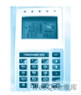
The following is a high-voltage soft starter liquid crystal control panel based on the single chip MSP430F149, which is used as an example to illustrate the application of MODBUS communication. The main device of MODBUS communication is the DSP controller, and the slave device is the liquid crystal control panel of the high voltage soft starter.
3.1 LCD panel MODBUS communication test code
/*****************************MODBUS communication test code ****************** *************
Summon to send:
00 06
00 00 00 0C 1E 88
Voltage and current monitoring functions:
00 03
1C 00 00 00 00 00 00 00 00 00 00 00 00 00 00 00 00 00 00 00 00 00 00 00 00 00 00 00 00 00 00 0D 8D
Fault display function:
00 02
18 01 01 01 01 01 01 01 01 01 01 01 01 01 01 01 01 01 01 01 01 01 01 20 34
*****************************MODBUS communication test code ***************** ************/
2: Explain the above test codes separately:
(1): Summon transmission, parameter setting function: communication between the controller (DSP) and the LCD screen (430) is bidirectional.
00 06
00 00 00 0C 1E 88
The above code is the summoning code that the DSP passes to 430. The meaning (code from left to right) is: 00: device code. In this system, the slave device only has one device of the high-voltage soft starter LCD panel, so the device code is set to 00. 06: function code, which function is implemented (in this example, 06 is the two-way call sending function, parameter setting; 03 function) The code realizes the voltage and current monitoring function; the 02 function code realizes the fault display function). 00 00: is the upper eight bits and lower eight bits of the starting address. 00 0C: is the number of 430 back-transmission bytes required by the DSP (excluding device code, function code, data number code, and check code), 00 is the upper eight bits of the number, and 0C is the lower eight bits of the number. 0C is hexadecimal (converted to decimal is 12, 12 is the number of "starting time, rated current - standby 3"), 1E 88: is the CRC check code. When the DSP gives 430
00 06
00 00 00 0C 1E 88
When the code is used, 430 first saves the 8 bytes into a temporary array RX[], and then judges the 8 bytes separately (1E 88 is the code obtained by checking the lookup table). If the check is correct, then The bytes to be passed back to the DSP are placed in the can_s[] array and sent to the DSP. The following code is 430 received
00 06
00 00 00 0C 1E 88
After the judgment is correct, the code is returned to the DSP. 00 06: It is the device code and function code. 18: The number of bytes returned (hexadecimal 18 is decimal 24). B6 8F is the check code of the return. The middle 24 bytes (00), each two bytes (00) correspond to "starting time, rated current - standby 3", the reason is all 00, because no parameters are set, set parameters on the LCD screen The corresponding high and low levels have also changed.
00 06
18 00 00 00 00 00 00 00 00 00 00 00 00 00 00 00 00 00 00 00 00 00 00 00 00 00 00 00 B6 8F
(2): Voltage and current monitoring functions:
00 03
1C 00 00 00 00 00 00 00 00 00 00 00 00 00 00 00 00 00 00 00 00 00 00
00 00 00 00 00 00 00 0D 8D
The same reason 00 03 1C is the device address, function code, the number of data that the DSP transmits to 430 (1C is hexadecimal, converted to decimal is 28, including 1C, excluding 00 03 0D 8D). When 430 received
00 03
1C 00 00 00 00 00 00 00 00 00 00 00 00 00 00 00 00 00 00 00 00 00 00 00 00 00 00 00 00 00 00 0D 8D
The received bytes are stored in an available array and displayed using the available array.
DSP downlink:
00 (device code) 03 (function code) 1C (number 14*2) 00H (voltage high) 00L (voltage low)
. . . . . . . . . . . . . . . . . . . . . . . . . . . . . . . . . . . . . . . . . . . .
00H (alternate 12 high) 00L (alternate 12 low) CRCH (high) CRCL (low)
(3): Fault display function:
00 02
18 01 01 01 01 01 01 01 01 01 01 01 01 01 01 01 01 01 01 01 01
01 01 01 20 34
The same reason 00 02 18 is the device address, function code, and the number of data that the DSP transmits to 430 (18 is hexadecimal, converted to decimal is 24, including 18 calculations, excluding 00 02 20 34). When 430 received
00 02
18 01 01 01 01 01 01 01 01 01 01 01 01 01 01 01 01 01 01 01 01 01 01 20 34
The received bytes are stored in an available array and displayed using the available array.
DSP downlink:
00 (device code) 02 (function code) 18 (number) 00 (in startup). . . . . . . . . . . . . . . . . . . . . .
. . . . . . . . . . . . . . . . . . . . . . . . . . . . . . 00 (three-phase unbalance) CRCH (high) CRCL (low)
High-voltage soft starter LCD panel
High-voltage soft starter LCD panel
Conclusion
Because MODBUS serial communication technology has the characteristics of simple implementation, low system integration cost and long communication distance (RS485/422), it is widely used in various industries. MODBUS communication also brings great convenience to the debugging staff and programmers on site. Therefore, with the development trend of multiple communication methods that can coexist and coexist, MODBUS serial communication technology will still maintain a wide application prospect.
CCTV Power Supply,CCTV Power Supply Box,CCTV DC Distributed Power Box
Chinasky Electronics Co., Ltd. , https://www.chinacctvproducts.com