Are you studying the battleground of 5G-RF front-end?
Discover the measurement of power amplifiers and RF front-end modules
Not as simple as imagined
Don't be afraid! Xiao Bian hereby presents the white paper on radio frequency testing technology
Help you overcome problems
The power amplifier (PA) is one of the indispensable radio frequency integrated circuits (RFIC) in modern radio. Whether as a discrete component or as part of an integrated front-end module (FEM), PA can significantly affect the performance of wireless transmitters. For example, the additional power efficiency (PAE) of a wireless PA will greatly affect the battery life of mobile devices, and its linearity will affect the receiver's ability to demodulate the transmitted signal.
Discrete components and integrated front-end modules
In the early days of the development of technologies such as GSM and UMTS, mobile devices usually provided independent amplifiers for each GSM and UMTS radio. However, the emergence of LTE and WLAN technologies and the use of more radio frequency bands have promoted the demand for more integrated radio frequency front-end technologies.
Now suppliers are trying to package more devices into a single component, including PA, low-noise amplifier (LNA), duplexer and antenna switch. Therefore, now the task of the RF test engineer is usually to test a highly integrated front-end module (as shown in Figure 1), rather than an independent PA. Although the measurement required for front-end module testing is basically the same as that of discrete components, testing integrated front-end modules usually requires additional steps to configure the device under test (DUT).
WLAN front-end module
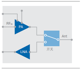
Figure 1. FEM usually integrates PA and LAN into the same component
When analyzing the performance characteristics of RF PA, engineers will use various measurement and test techniques to understand the gain, linearity and efficiency of the equipment. In actual operation, the specific measurements required to analyze the characteristics of the device depend on the intended use of the amplifier. For example, although parameters such as gain and efficiency are important for all PAs, devices used for wireless communication transmission still need to be measured against specific standards. Error vector magnitude (EVM), as one of the most important metrics for PA, is used to measure the quality of modulated signals, and adjacent channel leakage ratio (ACLR) is one of the most important measurement parameters for UMTS or LTE radio.
Gain and output power
Two important characteristics of radio frequency PA are gain and output power. Gain is used to express the relationship between the input power and output power of the device. Generally, when the gain of the PA remains relatively constant over a wide range of input power levels, when the output power approaches the saturation region of the device, the gain begins to decrease. This effect is called gain compression.
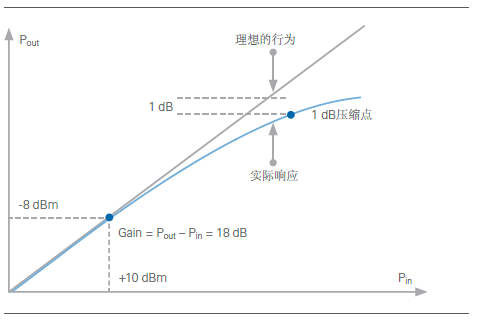
Figure 2. The relationship between input and output power in a typical PA
One of the most common methods to analyze the maximum available output power of a PA is to measure the 1dB compression point. As shown in Figure 2, the 1dB compression point refers to the operating point where the gain provided by the PA is 1dB smaller than the gain provided in the linear operating region. For example, if the gain of the PA in its linear operating region is 18dB, the 1dB compression point refers to the output power when the PA just provides 17dB of gain.
When testing the 1dB compression point, you can use a power-calibrated vector network analyzer (VNA) or a combination of an RF signal generator and an RF signal analyzer. Using a combination of RF signal generator and signal analyzer is the fastest way to measure the 1dB compression point. Continuous wave (CW) signal generator or vector signal generator (VSG) can be used for this measurement.
Gain can be measured as a function of input power. At this time, an RF signal analyzer can be used to measure the power level of the signal generator and measure the output power of the PA. As shown in Figure 3, one optimization technique available for production testing is to configure the VSG to generate a ramp waveform instead of a series of continuous waves (CW) with different power levels.
By using the vector signal transceiver (VSA) to collect the ramp signal, the input power and output power can be easily correlated to determine the relationship curve between gain and input power. This ramp signal method is much faster than configuring the signal generator for different steps, and can save valuable test time.
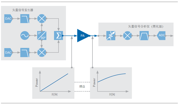
Figure 3. Using ramp signal to simulate PA to measure 1dB compression point
° Use NI vector signal transceiver to achieve fast power level servo controlThe unique technology adopted by NI PA test solution is to use NI vector signal transceiver (VST) to realize FPGA-based power stage servo. Traditional power-level servo control is a very time-consuming process. However, by implementing the control loop entirely on the instrument FPGA, the fastest power stage convergence can be achieved. If the power stage servo algorithm is separated from the embedded controller and executed on the FPGA, the test software can use the parallel measurement mechanism to perform parallel measurement, thereby significantly reducing the test time and test cost. For more information on using NI VST for fast power consumption measurements, please visit FPGA Servo Control for PA Testing (http://).
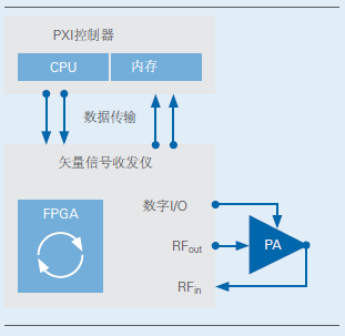
PXI system
An important technique to improve gain and power measurement accuracy is to use a small attenuator between the instrument and the PA under test. Using online fixed attenuators on PA input and output power can significantly reduce the power uncertainty caused by mismatch, as shown in Figure 4.
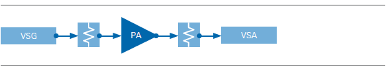
Figure 4. The attenuator between the instrument and the PA helps to optimize the mismatch uncertainty.
Calibrate power measurement with power meter
Use a power meter or VSA to measure the output power of the PA. In the past, power meters have become the most accurate power measurement method by measuring absolute power, with accuracy within ±0.2dB. But now, the vector signal analyzer (VSA) is equipped with on-board calibration standards and other tools, which can greatly improve the accuracy of measuring absolute power. A VSA, such as NI PXIe-5668R, can achieve a power measurement accuracy of ±0.4dB using only the on-board calibration function. If a reference calibration standard (such as a power meter) is used, a higher power accuracy can be achieved. Generally speaking, although the power meter can measure RF power more accurately than the VSA, the VSA has the following advantages in measuring the output power and gain of the device under test. First of all, VSA can use a single instrument for multiple measurements, which is convenient. In addition, compared with power meters, VSA can measure power faster. Because of this, in automated RF test applications, many engineers often use VSA in conjunction with a 1dB compression point to measure power.
An important step in measuring power and gain is to calibrate the system settings with a power meter. To complete this calibration step, first connect the power meter to the reference plane of the input terminal of the device under test, as shown in Figure 5. Using a power meter, we can measure the total output power of the signal generator, attenuator, and cable at various frequencies. After setting this step, we have obtained the characteristics of the signal generator within the power accuracy range of the power meter.
System calibration
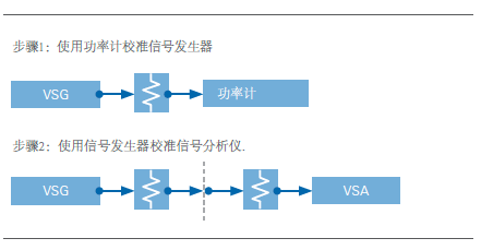
Figure 5. The system calibration is completed in two steps, namely, using the power meter to calibrate the signal generator and signal analyzer.
After the calibration signal generator is set up, you can directly connect the signal analyzer device to the signal generator device. The signal analyzer device includes instruments, cables, and attenuators. Using the calibration response generated by the signal generator and assuming that the measurement results made with the power meter are correct, the measurement offset of the signal analyzer device can be determined. After performing the above calibration steps, you can refer to the results of the power meter to measure the output power and gain more accurately.
° Use VNA to measure gainAlthough in automated test applications, the most common and fastest way to measure PA gain is to use VSG and VSA, VNA can also be used to measure PA gain. When using a two-port VNA to measure the gain of a PA, connect port 1 of the VNA to the PA input, and connect port 2 of the VNA to the PA output, and then measure the S21 coefficient. S21 is the gain of the PA.
A key issue in using a VNA to measure the gain of a PA is to ensure that the output power of the PA will not reach saturation or damage the VNA receiver. In this case, the amount of external attenuation will significantly affect the accuracy of the S21 measurement. Although the maximum safe input power level of many VNAs is usually in the order of 1W (+30dBm), when the instrument is operated close to the maximum power level, the measurement accuracy is usually reduced because the VNA can be compared with VSA. The programming attenuator range is usually narrower.
The use of VNA to accurately measure the PA requires attention to the power level at the input of port 2. Generally speaking, it is necessary to ensure that the source power of the PA and the input power of the VNA port 2 are basically equal. Therefore, if you want the PA to produce 20dB of gain, you should connect a 20dB attenuator between the output of the PA and VNA port 2, as shown in Figure 6.
No port saturation
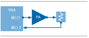
Figure 6. When using a VNA to measure PA gain, an attenuator can be used to prevent port 2 from reaching saturation.
An important difference between using an attenuator at the output of the PA and using an attenuator at port 2 of the VNA is the impact on the calibration reference plane. Whether using a short-circuit-open-circuit-load-through (SOLT) method or an automatic calibration kit to calibrate the VNA, the reference plane should be as close as possible to the device under test.
When using an external attenuator, the calibration of the measurement system should take into account the attenuator and all related cables and all connections in the path, as shown in Figure 7. In the case of using the attenuator in the signal path to calibrate the measurement system, the measured VNA S21 is the gain. For more information about VNA calibration, please visit ni.com to view an introduction to network analyzer measurements.
Understand the reference plane
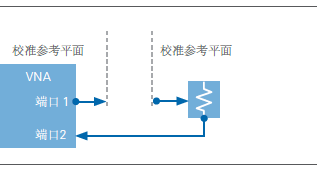
Figure 7. The VNA calibration reference plane must be extended beyond the external attenuator
Return loss and reverse isolation
Although the measurement of parameters such as gain does not technically require the use of a VNA, the measurement of return loss and isolation does require a complete network analysis. The instrument settings for return loss and reverse isolation depend on whether the small signal or large signal behavior of the PA is to be analyzed. Small signal refers to the signal in the linear working area, and large signal refers to the signal in the non-linear working area. When measuring small signal behavior, you can use VNA to accurately measure S11 (input return loss) and S22 (output return loss).
In some cases, measuring the output return loss may require fine-tuning the test configuration, as shown in Figure 8. The required attenuation between the PA output and VNA port 2 may be relatively high, especially for high-gain PAs. In this case, high PA gain and relatively low return loss will produce a very low-power reflected signal, which is measured by port 2 of the VNA. Therefore, accurate S22 parameter measurement of high-gain PAs usually requires the use of attenuators to generate lower losses than amplifier gains. In these cases, one attenuation value is usually used for S11, S12, and S21 measurements, and another attenuation value is used for S22 measurements.
° Use STS to quickly measure S parameters in production testingThe NI Semiconductor Test System (STS) is a fully automated production test system that uses a new method to measure production
S parameters in production testing. The system combines a port module and NI vector signal transceiver
(VST). In addition to the switch and preselection functions, the directional coupler included in the port module can effectively convert the VST
Convert to VNA. Therefore, S parameters can be quickly measured in a production test environment without the need to use other instruments
Device. S-parameter measurement uses a multi-port calibration module for calibration, which can automatically calibrate up to 48 RF terminals
mouth.
Measure S parameters
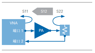
Figure 8. VNA can be used to measure reverse isolation and return loss
When testing PA under large signal conditions, the test configuration is much more complicated. Under large signal conditions, a large part of the output energy is converted into harmonics, which cannot be captured by traditional VNAs. Therefore, to fully analyze the large-signal performance characteristics of the PA, a large-signal network analyzer (LSNA) or load-pull test bench is required, as shown in Figure 9. Since it is more difficult to measure the S12 and S21 coefficients under large signal conditions, one solution is to measure the S21 coefficient performance as a function of input and/or output impedance. In this case, the programmable tuner is placed at the input or output of the device under test.
Basic load-traction test configuration
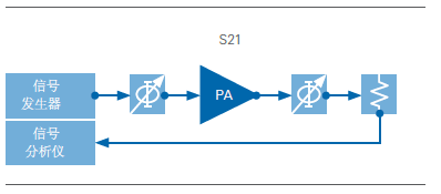
Figure 9. Schematic diagram of basic load-traction test configuration
Although this method cannot directly measure the input impedance (S11) or output impedance (S22), it is possible to estimate the input/output impedance that maximizes the performance or efficiency of the PA through trial and error. It should be noted that the typical configuration is to use a CW signal generator to supply power and use a power meter for measurement. Now you can use the VSG to generate the modulated signal, and use the VSA to analyze the modulated signal, and then measure the large signal performance of the PA.
Digital Display Test Pen ,Power Tester Pen,Voltage Pen,Digital Voltage Tester
YINTE TOOLS (NINGBO) CO., LTD , https://www.yinte-tools.com