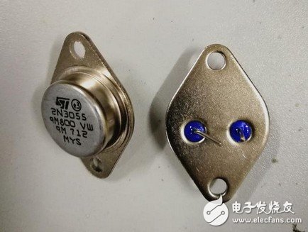
This time we used a larger power transistor 2N3055, and only two resistors are used, and it is better to select a larger power of the resistor, so that the output power of the circuit will increase accordingly...
In the past, we published some articles about inverters, which are only theoretical explanations and rarely practiced. One of the most important reasons is that there is no material, but I also want to test the feasibility of the circuit for everyone. That mood is unmatched by how many finished products are bought. The theme of our production is still how simple it is. This circuit has been tested and successfully tested, and the article will share the test results with everyone.
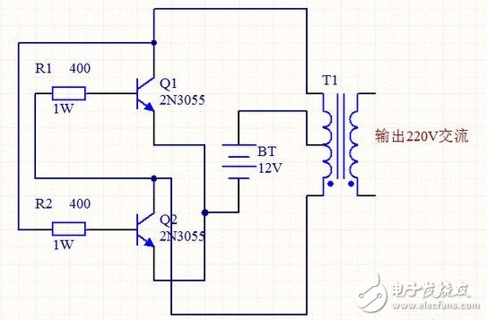
Inverter schematic
The picture above is our inverter schematic. This time we used the larger power transistor 2N3055, and only two resistors are used, and the power of the resistor is selected to be larger, so the output power of the circuit will be correspondingly Increase, the above figure uses a 1W 400 ohm resistor, if there is no 1W, it does not matter, the most used is the 1/4W resistor, as long as the choice of four resistors in parallel is about 400Ω.
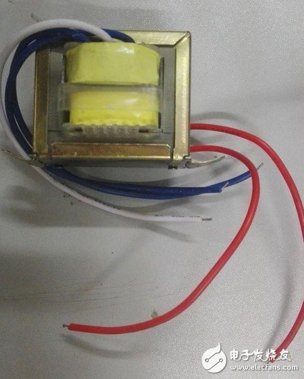
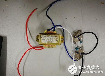
The above picture is two components that are not easy to see. The first picture is a transformer with a shaft head. The power of the transformer used here is 10W. The power is small and can hardly drive any load. After you make it, you can use the LED light to go. test.
Many friends want to know the working principle. This is actually a oscillating circuit, which turns the DC power into AC power, then turns it into 220V through the transformer boost, and then connects the electrical device to the output terminal, but it is made on these components. Inverter, the output waveform certainly has no grid standard, but driving the bulb is sufficient.
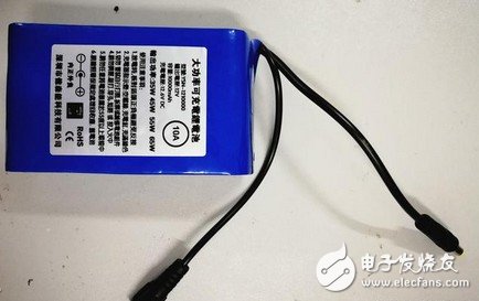
This is a 12V power supply, the output power can reach 65W, if you have more power solar panels or power supply in your home, you can use it directly, but pay attention to the voltage needs to be 12V, you can connect the circuit after finding these components.
Inverter actual connection
The figure above is the actual connection circuit diagram. You can see that the resistor is composed of four 1/4W resistors in parallel. However, due to the low power of this transformer, these four components are also used in parallel, and the components are taken according to the schematic. Electrical connection can be made after the final inspection is correct, but it must be noted that the output voltage has exceeded the human safety voltage, and safety measures should be taken during operation.
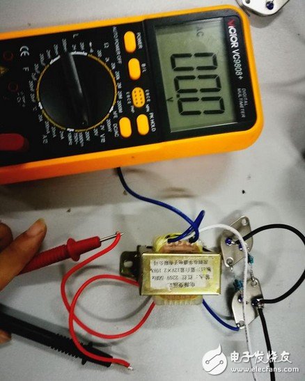
Test circuit feasibility
Here, the small series uses a multimeter to demonstrate the test, because there is no suitable electrical appliance, and the power of the transformer can not drive the high-power electrical appliances, so use a multimeter instead of the electrical appliance to test the output voltage. Turn the multimeter to the appropriate gear, do all the work, turn on the power and observe the multimeter's reading.
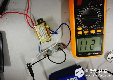
After the power is turned on, you can hear the signal oscillating sound. At this time, the voltage display can be read on the multimeter. This is 211V, and it is very stable.
The advantage of USB Cable Type C is that it supports higher current, that is that more current can be passed by Type-C in the same time. In this way, the charging speed of the device can be accelerated. At present, the charging current of most Type-C data lines is generally 2A. If the charging rate of 3A is to be reached, a high-current wall charging matching it is required. That is to say, if the wall charge only supports 1A, whether it is charged with 2A or 3A data line, there is no difference fundamentally. If the current supported by the wall charging is 2A, and the type-C data cable of 2A/3A is matched, the effect can be significantly changed.
In addition, the device equipped with the Type-C interface can be charged by connecting the mobile power supply through the Type-C cable or Usb C Cable. Users do not need to carry the charging cable, but can have the wall charging and Type-C cable. In addition, when selecting a Type-C charging cable, We should pay attention to the current limit. The charging data cable 1A does not have fast charging performance, 2A is the most commonly used Type-C charging data line, and 3A is the best data line at present. If you want to have fast charging effect, you must choose the Type-C charging data line with 3A current.
The highlights of Type-C interface are thinner design, faster transmission speed (USB3.1 up to 10Gbps) and stronger power transmission (up to 100W).The biggest feature of Type-C double-sided plugable interface is that it supports double-sided insertion of USBinterface. Officially solved the USB never insert the worldwide problem, the front and the back of the random plug.The USB Cable used with it must also be thinner and lighter.

Usb Cable Type C,Usb Type C Cable,Type C 3.0 Cable,Usb Type C Data Cable
Henan Yijiao Trading Co., Ltd , https://www.yijiaousb.com