If you drive an op amp with a certain source resistance, the equivalent noise input is equal to the square root of the sum of the following: the voltage noise of the amplifier; the voltage generated by the source resistor; and the current noise generated by the amplifier flowing through the source impedance. Voltage.
If the source resistance is small, the noise generated by the source resistor and the current noise of the amplifier have little effect on the total noise. In this case, the noise at the input end is actually only the voltage noise of the operational amplifier.
If the source resistance is large, the Johnson noise of the source resistance may be much higher than the voltage noise of the operational amplifier and the voltage generated by the current noise. However, it should be noted that since Johnson noise only grows with the square root of the resistance, and the noise voltage affected by current noise is proportional to the input impedance, the current noise of the amplifier will dominate if the input impedance is sufficiently high. When the amplifier's voltage and current noise are high enough, Johnson noise will not dominate at any input resistance.
If the noise contribution of an amplifier is negligible relative to the source resistance, it can be selected by the op amp's quality factor Rs, op. This can be calculated from the noise figure of the amplifier:
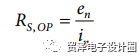
Where: en represents the voltage noise in the input to the input end, in which the current noise is converted to the input end.
Figure 1 shows the voltage noise density vs. RS, OP vs. RS, OP for various ADI high voltage (up to 44 V) op amps at 1 KHz, 1 kHz. The slash shows the Johnson noise associated with the resistance.
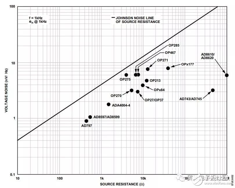
Figure 1. Amplifier noise plot for ADI

A similar plot can be made for a selected frequency based on the data in the op amp data sheet. For example, the AD8599's voltage noise at the input end is about 1.07 nV/√Hz, and the current noise equivalent to the input terminal is 2.3 pA/√Hz (1 kHz). Its Rs, op value is approximately 465 S2 (1 kHz). In addition, you need to pay attention to the following points:
The Johnson noise associated with the device is equivalent to a source resistance of approximately 69.6 Ω (see Figure 1);
For source resistances exceeding 465 Ω, the noise current generated by the amplifier current noise exceeds the noise voltage generated by the source resistor; the current noise of the amplifier becomes the dominant noise source.
To use this diagram (see Figure 2), perform steps 1 through 4.
1. Normally, the source resistance is known (eg sensor impedance). If the resistance value is not known, it is calculated according to the surrounding or front-end circuit device;
2. Determine the position of the given source resistance on the Johnson noise line, such as 1 kΩ;
3. Draw a horizontal line from the point determined in step 2 to the right side of the graph;
4. Draw a straight line from the point determined in step 2 to the lower left. The slope is 10 times lower for every 10 times lower voltage noise.
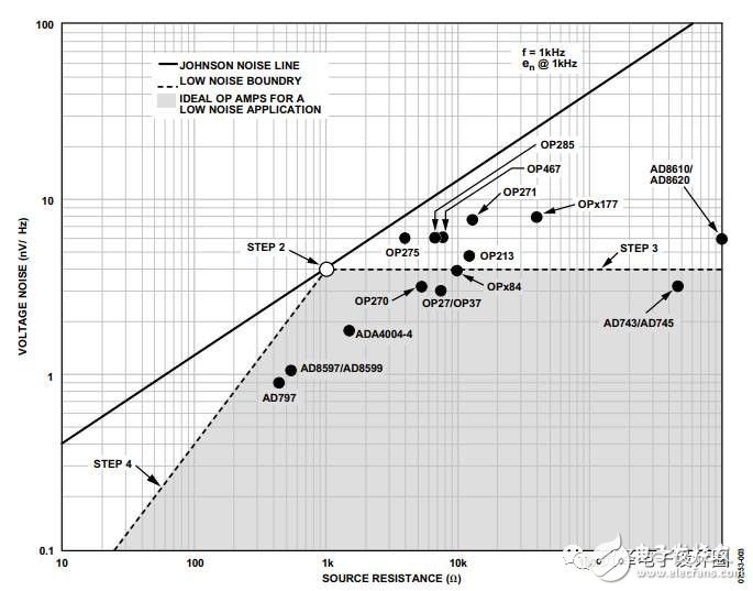
Figure 2. Selecting an op amp for a low noise design
The amplifiers located at the bottom right of the line are high quality low noise op amps for the target design, as shown in the shaded part of Figure 2.
Knock on the blackboard! The focus is coming!
All potential noise sources should be considered when evaluating amplifier noise performance for low noise designs.
The main noise contribution of an op amp depends on the source resistance as follows:
Rs > > Rs, op; the current noise equivalent to the input end is dominant
Rs = Rs, op; amplifier noise is negligible; resistance noise dominates
Rs <<Rs, op; voltage noise proportional to the input terminal dominates
In summary, interference signals can be reduced or eliminated by:
Good wiring technology to reduce parasitic effects
Good grounding techniques such as digital grounding and analog ground isolation
Good shielding
For resistive noise sources, follow these rules:
Limit bandwidth based on application needs
Reduce the resistance as much as possible
Use low noise resistors such as resistors with large foil, wirewound and metal film technology
Minimize the number of resistive noise sources
1-Piece Fixing Tie For Weld Stud
1-Piece Fixing Tie For Weld Stud,Weld Screw Zip Tie,Zip Tie Screw Mount,Wire Harness Automatic Cable Tie
Wenzhou Langrun Electric Co.,Ltd , https://www.langrunele.com