Siemens plc special sign relay (SM)
Some auxiliary relays have special functions or state variables of the storage system, related control parameters and information, which we call special sign relays. The user can communicate the information between the PLC and the controlled object through special signs. For example, the device status and operation result information during the running of the program can be read, and the program is used to implement certain control actions. The user can also implement certain functions by directly setting some special flag relay bits.
The special mark relay is indicated by "SM", and the special mark relay area has bit, byte, word and double word operation modes according to functions and properties. Among them, SMB0 and SMB1 are system status words, which can only read the status data, cannot be rewritten, and can be bit-addressed. Some commonly used flag bits in the system status word are described below:
SM0.0: always on;
SM0.1: The first scan is 1, and the next is 0, which is often used to initialize the program;
SM0.2: This bit is set to 1 when the result of the machine performing a mathematical operation is negative;
SM0.3: Enter RUN mode after power on, this bit is set to 1 scan cycle;
SM0.4: This bit provides a clock pulse with a period of 1 minute, and 30 seconds is 1, 30 seconds is 0;
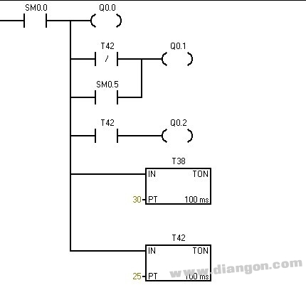
SM0.5: This bit provides a clock pulse with a period of 1 second, 0.5 seconds for 1 and 0.5 seconds for 0;
SM0.6: This bit is the scan clock pulse. This scan is 1 and the next scan is 0.
SM1.0: When some instructions are executed, the result is 0, the position will be changed to 1;
SM1.1: When certain instructions are executed, the result overflows or is illegal, the position will be changed to 1;
SM1.2: When a mathematical operation instruction is executed, the result is a negative number, and the position is changed to 1;
SM1.3: When attempting to divide by 0, the position will be changed to 1;
Usage of SM0.0 in S7-200:
1. SM0.0 is always ON when the program is running.
2. SM0.0 is an unconditional normally closed contact that is used to initiate an unconditional operation.
As long as the power is on, SM0.0 must be "1". Therefore, the instructions in the program that are not subject to any conditions and must be executed are used as trigger contacts.
3. Q: The program sometimes needs to add SM0.0 before the instruction. Why is it not directly connected to the bus, is it the same?
Best answer:
Because the instructions of the S7-200 cannot be directly connected to the "busbar", this does not meet the grammar requirements.
SM0.0 is an uncontrollable contact for unconditional triggering. Not every instruction requires SM0.0. In other cases, controllable contacts are used to trigger commands, such as I0.0, M0.0, or various comparison instructions. If no controllable contacts are available, only SM0.0 can be used.
Other answers:
a, S7200 programming has provisions, there must be contact instructions before the output class instructions, sometimes the output instructions do not require conditions to directly output as 1, but in order to meet such programming conventions, the string of often 1 is sm0.0 front.
b. Different PLC manufacturers have their own grammar rules. The SIEMENS S7-200 ladder diagram is required in this way. The bus line cannot be directly connected to the output command (or subroutine call).
c, a program does not need SM0.0 in many aspects, if you do not need to be able to complete the control requirements, then of course not good. But for some instructions you still can't use it! In addition, it is still a good helper when debugging the program!
Basic instruction one about status word (SM)
01 SMB0 includes 8 status bits (SM0.0/SM0.1/SM0.2/SM0.3/SM0.4/SM0.5/SM0.6/SM0.7)
02 SMB1 contains a variety of potential error prompts that can be automatically set or reset by the system when certain instructions or execution errors occur.
03 SMB2 Free interface receives buffers of characters during free interface communication.
04 SMB3 When the free interface communicates, it can be set to SM3.0 when there is a parity error in the received characters.
05 SMB4 flag interrupt queue overflow or communication interface usage status.
06 SMB5 logo I/O system error.
07 SMB6 CPU Module Identification (ID) Register.
08 SMB7 system reservation
09 SMB8-SMB21 I/O module identification and error registers, in byte pair format (two adjacent bytes), store module type, I/O type, I/O points and measured values ​​of expansion module 0-6 Module I/O error.
10 SMB22-SMB26 Record system scan time.
11 SMB28-SMB29 Stores the digital quantity corresponding to the analog potentiometer that comes with the CPU module.
12 SMB30-SMB130 SMB30 is the communication mode control byte of free interface 0 when free interface communication; SMB130 is the communication mode control byte of free interface 1 when free interface communication; two bytes are readable and writable.
13 SMB31-SMB32 Permanent Memory (EEPROM) Write Control.
14 SMB34-SMB35 Time interval for storing timed interrupts.
15 SMB36-SMB65 High-speed counters HSC0, HSC1, HSC2 monitoring and control registers.
16 SMB66-SMB85 High Speed ​​Pulse Output (PTO/PWM) Monitoring and Control Register.
17 SMB86-SMB94 Free interface communication, interface 0 or interface 1 receives the information status register.
18 SMB186-SMB194 When free interface communication, interface 0 or interface 1 receives the information status register.
19 SMB98-SMB99 flag expansion module bus error number.
20 SMB131-SMB165 High-speed counters HSC3, HSC4, HSC5 monitoring and control registers.
21 SMB166-SMB194 High Speed ​​Pulse Output (PTO) Envelope Definition Table.
22 SMB200-SMB299 is reserved for the smart expansion module to save its status information.
The plate-grid is a kind of Printer Accessories.
The cartridge is irradiated by laser beam to adsorb toner, and then the toner is hot pressed by fixing roller for printing. In this process, there will be part of toner residual, which can not be "granules returned to the warehouse"; Automatic cleaning function is not adsorbed new toner particles and directly print, will remain toner away, fully ensure the next printing effect. And the plate-grid plays an important role. When high voltage generator to a high voltage electrode, wire electrode with reseau formed between a strong electric field, and release the corona, wire electrode and the photosensitive drum ionizes the air between the air ions migrate to the drum surface, make the photoconductor (drum) surface is full of charge, so can spare toner "adsorption to warehouse", so as to save toner, The purpose of reducing environmental pollution.
Printer Plate-Grid is widely used in high-end Printer, photocopier, laser printer cartridge. Our charging network plate grid is made by SUS304 stainless steel. We use fine metal etching process, and we can guarantee that the etched plate grid has dense charging network, small diameter, etching straight lines, no broken lines and no notch. We custom Plate-Grid with drawings provided by customers.
Custom Plate Grid,Etched Plate Grid,Printer Plate-Grid,Charging Network Plate Grid
SHAOXING HUALI ELECTRONICS CO., LTD. , https://www.cnsxhuali.com