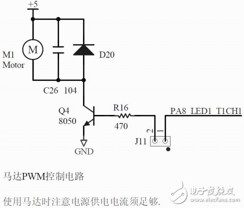
The advanced timer is similar to the general-purpose timer. Below is a TIM1 PWM program. TIM1 is the STM32's only advanced timer. There are 4 channels with dead zones complementary.
First configure the IO pin:
GPIO_InitTypeDef GPIO_InitStructure;
GPIO_InitStructure.GPIO_Pin = GPIO_Pin_8;
GPIO_InitStructure.GPIO_Mode = GPIO_Mode_AF_PP;
GPIO_InitStructure.GPIO_Speed ​​= GPIO_Speed_50MHz;
GPIO_Init(GPIOA, &GPIO_InitStructure);
GPIO_InitStructure.GPIO_Pin = GPIO_Pin_13;
GPIO_InitStructure.GPIO_Mode = GPIO_Mode_AF_PP;
GPIO_InitStructure.GPIO_Speed ​​= GPIO_Speed_50MHz;
GPIO_Init(GPIOB, &GPIO_InitStructure);
RCC_APB2PeriphClockCmd(RCC_APB2Periph_TIM1, ENABLE);
RCC_APB2PeriphClockCmd(RCC_APB2Periph_GPIOA, ENABLE);
RCC_APB2PeriphClockCmd(RCC_APB2Periph_GPIOB, ENABLE);
TIM_TimeBaseInitTypeDef TIM_TimeBaseStructure;
TIM_OCInitTypeDef TIM_OCInitStructure;
Void Tim1_Configuration(void)
{
TIM_TimeBaseInitTypeDef TIM_TimeBaseStructure;
TIM_OCInitTypeDef TIM_OCInitStructure;
TIM_DeInit(TIM1); //Reset to default value
TIM_TimeBaseStructure.TIM_Prescaler = 4000; //Prescaler (clock division) 72M/4000=18K
TIM_TimeBaseStructure.TIM_CounterMode = TIM_CounterMode_Up; // Count up
TIM_TimeBaseStructure.TIM_Period = 144; //Load value 18k/144=125hz means that the top 144 is full.
TIM_TimeBaseStructure.TIM_ClockDivision = TIM_CKD_DIV1; //Set the clock segmentation does not know no matter
TIM_TimeBaseStructure.TIM_RepetitionCounter = 0x0; //The period counter value does not know no matter
TIM_TimeBaseInit(TIM1,&TIM_TimeBaseStructure); //Initialize the time base unit of TIMx
TIM_OCInitStructure.TIM_OCMode = TIM_OCMode_PWM2; //PWM mode 2
TIM_OCInitStructure.TIM_OutputState = TIM_OutputState_Enable; //Forward channel valid PA8
TIM_OCInitStructure.TIM_OutputNState = TIM_OutputNState_Enable; //The reverse channel is also valid PB13
TIM_OCInitStructure.TIM_Pulse = 40; //40 of the duty time 144 is high, the complementary output is just the opposite
TIM_OCInitStructure.TIM_OCPolarity = TIM_OCPolarity_Low; //Output polarity
TIM_OCInitStructure.TIM_OCNPolarity = TIM_OCNPolarity_Low; //polarity of the complementary end
TIM_OCInitStructure.TIM_OCIdleState = TIM_OCIdleState_Reset; //Non-working status in idle state
TIM_OCInitStructure.TIM_OCNIdleState = TIM_OCIdleState_Reset; //No matter
TIM_OC1Init(TIM1,&TIM_OCInitStructure); //Number initializes peripheral TIMx channel 1 here 2.0 library is TIM_OCInit
TIM_Cmd(TIM1,ENABLE);
TIM_CtrlPWMOutputs(TIM1,ENABLE);
}
/ / Set the capture register 1
Void SetT1Pwm1(u16 pulse)
{
TIM1-"CCR1=pulse;
}
/ / Add a keyboard scan in MAIN to change the duty cycle
#include "STM32Lib\\stm32f10x.h"
#include "hal.h"
Extern void SetT1Pwm1(u16 pulse);
Int main(void)
{
U16 pulse=40;
ChipHalInit (); / / on-chip hardware initialization
ChipOutHalInit (); / / off-chip hardware initialization
For(;;)
{
If(GET_UP())
{
While(GET_UP());
If(pulse"=144)
{
Pulse+=5;
SetT1Pwm1(pulse);
}
}
If(GET_DOWN())
{
While(GET_DOWN());
If(pulse 30)
{
Pulse-=5;
SetT1Pwm1(pulse);
}
}
}
}

Aluminum Alloy Die Casting Blank
Aluminum Alloy Die Casting Blank,Pressure Die Cast,Die Casting Products Alloy,Molded Precision Die Parts Cast
Dongguan Metalwork Technology Co., LTD. , http://www.diecast-pro.com