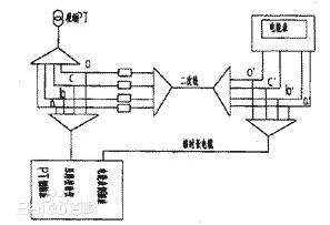
Secondary circuit Definition: All low-voltage loops such as measurement loops, relay protection loops, switch control and signal loops, operating power loops, circuit breakers, and electrical blocking circuits for disconnectors. Secondary circuits are interconnected by secondary devices to form a secondary circuit that monitors, controls, regulates, and protects the primary device. It is a circuit that is connected to the secondary winding of a transformer, a measurement monitoring instrument, a relay, an automatic device, etc. in the electrical system through a control cable. It is used to control, protect, adjust, measure and monitor the operating conditions of each parameter and each component in the primary circuit. The circuits used to monitor the electrical connections of the meter, control signal, relay protection, and automatic devices are called secondary circuits or secondary wiring.
Secondary circuit classificationAccording to the nature of power:
AC current loop --- All circuits of all current components such as the current coil of the measuring instrument and relay supplied by the secondary side of the current transformer (TA).
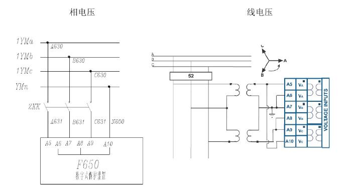
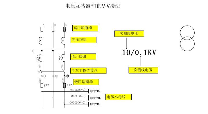
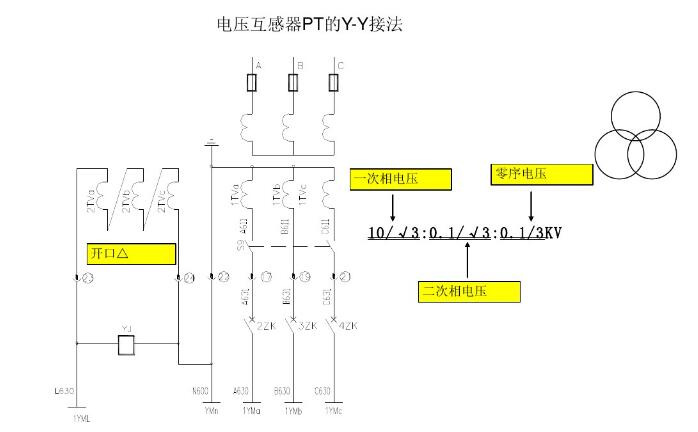
AC voltage loop --- from voltage transformer (TV) secondary side and three-phase five-pole voltage transformer opening delta via step-up transformer to 220V power supply for measuring instruments and relays and other voltage coils and signal power supply.
DC circuit—Use the DC power source with variable output and rectified output.
Battery---Applicable to large and medium-sized transformers and power distribution stations, with high investment cost and large floor space.
By purpose:
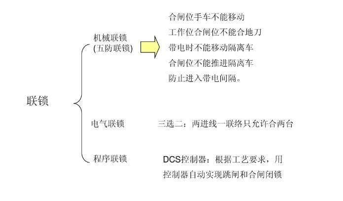
Electrical blocking of measuring circuits, relay protection circuits, switch and signal circuits, circuit breakers and disconnectors
Loop, operation power circuit.
Actuation circuit --- from the operation (operation) of the power supply to the circuit breaker, closing all the relevant components between the coil, such as: fuses, control switches, intermediate relay contacts and coils, terminals and so on.
The signal circuit—including the circuit board of light codes and the audio circuit (alarm bell, electric whistle) is relayed from the signal relay and protection element to the central signal panel or from the actuator to the central signal panel.
The commonly used relay protection wiring diagram includes: the relay protection principle is connected to the coil, the principle of the secondary circuit development diagram, construction drawings (secondary circuit, also known as the back wiring diagram, disk layout).
1, see the figure
A, 'First look once, then look two times'. Once: circuit breakers, disconnectors, current, voltage transformers, transformers, etc. Understand the function of these devices and commonly used protection methods, such as transformers generally need to install over-current protection, current short-circuit protection, overload protection, etc., to grasp the basic principles of various protection; then find the conversion of primary and secondary equipment, transmission components, The effect of one change on secondary changes, etc.
B, 'Look at the exchange and see DC'. Refers to the first look at the secondary wiring diagram of the AC circuit, and the characteristics of changes in the amount of electricity, and then by the exchange of the 'cause' to find out the DC loop 'fruit'. The general AC circuit is relatively simple.
C, 'AC look power, DC find coil'. Refers to the AC circuit generally starting from the power supply, including AC current, AC voltage loop in two parts; first find out which current transformer or which group of voltage transformer power supply (current source, voltage source), the transformation of the current, voltage from The role of their relationship with the DC loop, the corresponding electrical quantity reflected by which relay.
D, 'coil check contacts, contact wires into a line'. After finding the coil of the relay, find the loop where the corresponding contact resides. Normally, the contact is connected to another circuit; this loop may be connected in series with other relay coils, and the coils of other relays It causes its contact to switch on to another circuit until the secondary circuit's pre-set logic function is completed.
E, 'Looking up, down, left and right order, the device outside the screen is connected.' Mainly for expansion plans, terminal layouts, and post-screen equipment installation drawings. In principle, from the top down, from left to right, at the same time with the device outside the screen to see together.
2, schematic
The part of the primary wiring directly connected to the secondary circuit is drawn in the form of three lines, and the rest is expressed as a single line diagram. The schematics are mostly used to learn and analyze the principle of relay protection devices and automatic devices or as the original basis for the design of secondary circuits.
A. The schematics of the instruments and relays are represented by the overall form of the device's graphical symbols, but the internal circuit diagrams are not drawn and only the contacts are drawn.
B. The schematic diagram is to draw the current loop, voltage loop, DC loop and primary loop diagram of the secondary part together; the feature is to enable the reader to have an overall concept of the entire device structure and to clearly understand the The electrical connection and the principle of operation of the equipment in the secondary circuit.
C. Disadvantages: Some details of secondary wiring are not comprehensive, and there is no internal wiring of components. The terminal strip number, loop number, and wire indication are only a few, and only the polarity of the DC power supply is marked.
3, expand the map
The expansion diagram and the schematic diagram are two expressions of the same wiring. 'Intuitive'
A. The equipment of the secondary circuit is developed and divided into AC current, AC voltage loop, DC loop, and signal loop.
B. Connect different devices according to circuit requirements to form separate circuits.
C. The coils and contacts of the same device (electrical device) are represented by the same letter symbol. When there are many devices of the same type, the serial number is used.
D. The right side of the development diagram shows the use of the circuit in words.
E. The contacts of all components in the development diagram are represented in the normal state, that is, no action has taken place.
4, installation wiring diagram
A. The screen at the back of the screen --- The structure of the screen is displayed on the installation wiring diagram as a plan view. The rear part of the screen is equipped with instruments, control switches, signal devices and relays; the terminal panel is installed on the side of the screen; the back side or side of the screen top is equipped with a small bus, fuses, additional resistors, knife switches, bells, buzzer, etc.
B. General rules for on-screen equipment layout --- Mostly relays, intermediate relays, time relays, lower relays (directional, differential, recloser, etc.) that are often required to be debugged, and signal relays, connection tabs And optical cards, lights, buttons, control switches and so on.
C. Protection and Control The secondary devices on the screen map are numbered from left to right and top to bottom, and the text symbols are marked; the text symbols are consistent with the symbols on the unfolded and schematic diagrams; on-screen Next to the drawing, the equipment table on the screen is listed (in the equipment list, the order number, symbol, name, model number, technical parameter, quantity, etc. of the equipment are indicated); for example, the equipment is installed behind the screen (eg resistors, fuses, etc.) , indicate in the remarks column of the equipment table.
D. In the wiring diagram of the installation shows the secondary device --- In the wiring diagram at the back of the screen, the left and right direction of the device is just opposite to the screen layout (back view); the outline of the secondary device that cannot be seen behind the screen is drawn with a dotted line. The slightly complicated internal wiring of the device (such as various relays) is also drawn, while the ammeter and power meter are not drawn.
Terminals (screws) are drawn from the inside of each device. Use a small circle to draw and indicate the terminal number.
5, terminal blocks
Connect different devices circuits on the same screen (except special signal contact).
A, test terminals --- for the need to invest in the current loop of the test instrument is available, mainly to use it to verify the accuracy of the meter and relay in the current loop, to ensure that the secondary side of the current transformer is not in the test Will open the way and do not have to loose the original wiring.
B. Connecting test terminals --- At the same time with the function of connecting terminals and test terminals, it is often used in current test circuits that need to be connected to each other.
C. Special terminals - used in applications where it is necessary to switch the circuit easily.
Distribution application cable cross-sectional area (copper core) current loop ≥ 2.5MM2, long length should be ≥ 4 ~ 6MM2 voltage loop, control loop, signal loop ≥ 1.5MM2
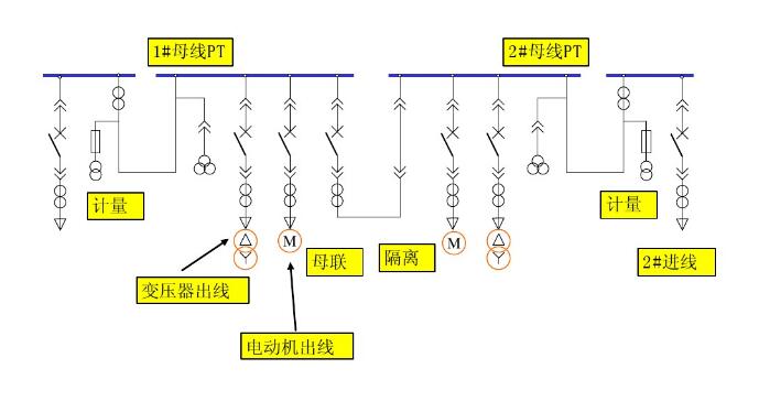
High-voltage secondary schematic classificationPower line
PT and arrester
Bus contact
Isolated handcart
Outlet (feeder)
Transformer outlet
Motor outlet
Generator outlet
Capacitor outlet
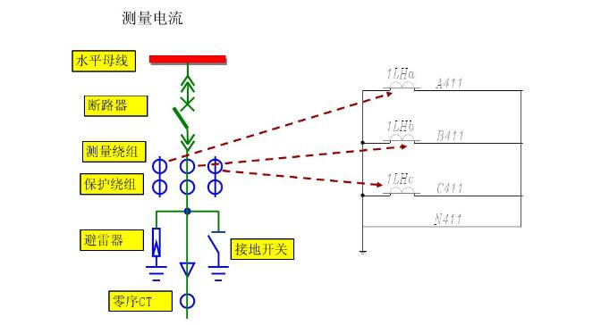
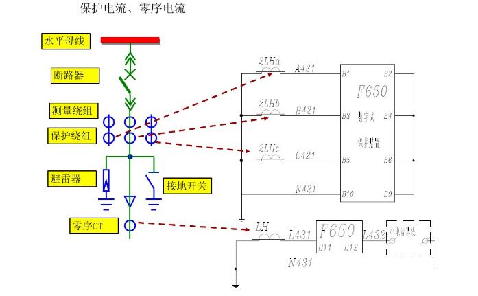
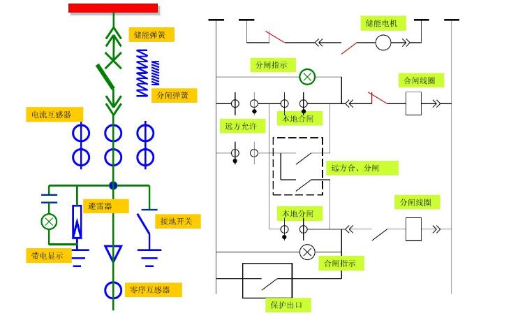
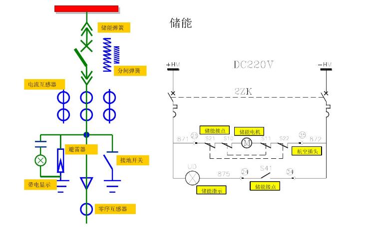
1, sampling loop
2, the control circuit
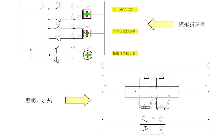
3, auxiliary circuit
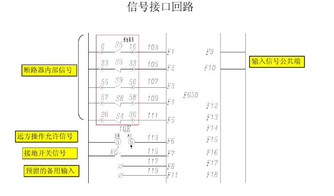
4, signal interface circuit
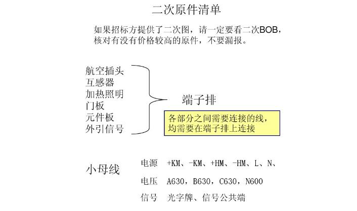
5, the original list BOM
6, terminal block
7, small bus
16+ Years Experience Smart Watch manufacturer, ITOPNOO Provide One-stop Smart Wearable devices Solutions For You.
Our Smart Wearable products include android smart watches, Watch For iPhone, Bracelet and Wristband etc.
Leading healthcare navigation services for individuals and families who are generally healthy or face serious medical issues, and health services for employers.
The Trends New Watches Designs. Custom smart watch products designed with the vision of our clients' brands in mind.
Wholesale smart watches,Best Smart Watches,Gifts Wholesalers, smart watch manufacturer
TOPNOTCH INTERNATIONAL GROUP LIMITED , https://www.mic11.com