Someone asked me a question and attached a SPICE simulation schematic (thanks to that!). It is an op amp circuit (specifically what kind of circuit is not important), the point is that the op amp circuit includes some bypass capacitors on the power supply pins. Of course, this may be because the engineer's simulation program is directly imported into the board layout program. These bypass capacitors are critical in the final circuit. But does the simulation need them? Using them is of course not harmful, but it is not needed. From DC to THz, the SPICE voltage source at zero impedance is already "perfect" and does not require any bypass capacitors. The next two circuits are identical in SPICE. The left power supply bypass capacitor has no effect; the right power supply and ground long contacts do not degrade the simulation performance. However, there are huge differences on your board.
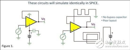
If your board layout does not use a valid bypass method at the appropriate location on the board, ie without bypass capacitors, you may not get the desired performance. Or you may face an annoying oscillation problem. Don't blame SPICE simulation; it's impossible to find out for you. Even if you model the poor power supply bypass with series resistors and inductors, the macro model may not be able to accurately model the adverse effects. On the power supply pins, the signals interact with each other and may cause oscillation. This situation is complicated and you should not try to model it. In fact, some old macros don't even model the output current as current from the power supply. Some of the new macro modes we offer are excellent enough to simulate the amplifier's suppression of power supply noise, but it is not able to correctly model the possible instability or oscillations. In some of our IC designs, we usually model these effects. We performed a very detailed simulation of the entire circuit—including each transistor, resistor, and capacitor. Parasitic components such as lead inductance and on-chip line resistance and capacitors with different board layouts are included. Therefore, we often model the effects of imperfect power supplies in order to see how it affects the device. However, this fineness has exceeded the extent to which the macromodel can be simulated.
It's a good idea to emulate your amplifier circuit using a SPICE macro mode, which gives you a clear idea of ​​what happens when many circuits are working. Most of the latest macros we offer, the "Green-Lis" version, are excellent and are indeed the best and most complete macros in the industry. But they are just macro models. They cannot simulate all the behavior of the circuit. In addition, they are not responsible for poor circuit layout and power supply bypass.
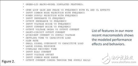
Reading the op amp-related text files (see Figure 2) gives you a clear idea of ​​some of the performance attributes and performance included in our macro mode. For many years, we have been providing users with a macro model list. In our TINA-TI version of the free SPICE program, you can view the details by double-clicking on the schematic symbol and clicking on "Enter Macro". Some macromodels more than a decade ago should not be too complicated and may not be included in this list.
Recommended reading: How to use SPICE to simulate high-precision digital-to-analog converters?
The 1U Brush Cable Management Panel mounts to a standard 19" rack to organize cables while keeping dust and dirt out of the rack. Constructed of high-quality steel with high-density nylon bristles, the 1U brush plate creates a clean looking point of entry and offers cable separation for simple cable organization. The brush panel also promotes proper airflow through the rack by closing off open spaces between equipment, this cable organizer comes complete with 2 sets of rack screws for easy installation.
Brush Type Cable Management,Brush Cable Management,1u brush panel,1U Cable Management
NINGBO UONICORE ELECTRONICS CO., LTD , https://www.uniconmelectronics.com