There are many types of USB devices on the market, but these devices will have some common characteristics. According to these characteristics, USB devices can be divided into different categories, such as display devices, communication devices, audio devices, mass storage devices, and human-machine interfaces. Equipment (HID). Here is how to implement HID class devices and how to access HID class devices in the application. Starting from the Windows98 operating system, a universal driver is provided for HID devices, so as long as the device firmware program is written according to the HID device class specifications, the Windows system can automatically identify the device, eliminating the complicated driver writing process.
1 Introduction to HID protocol
Human-machine interface devices (HID) mainly refer to devices that some people interact with computers, such as keyboards, mice, joysticks, etc .; but HID devices do not have to be these human-computer interaction devices, as long as they meet the requirements of HID device-level definition specifications Can be considered as HID devices. HID equipment has the following main features:
â‘ The exchanged data is stored in the report structure, and the device must support the HID report format.
â‘¡ Each transaction can carry small or medium amounts of data. Low-speed devices have a maximum of 8 bytes per transaction, full-speed devices have a maximum of 64 bytes, and high-speed devices have a maximum of 1,024 bytes
③ There is a limit on the maximum transmission speed. A low-speed device has a maximum transaction of 10 ms and a maximum speed of 800 B / s; a full-speed device has a maximum transaction of 1 ms and a maximum speed of 64 KB / s; a high-speed device has a maximum transaction of 125 μs and a maximum speed of 24.576 MB / s.
â‘£ There is no guarantee of transmission speed.
When a USB device is inserted, the host will request various descriptors from the device to identify the device. In order to identify a device as a HID category, the device must comply with the HID specification when defining the descriptor. Figure 1 shows the relationship between the various descriptors of HID. In fact, each device can have multiple interface descriptors to implement a multi-interface device, and there should be multiple endpoint descriptors under each interface descriptor.
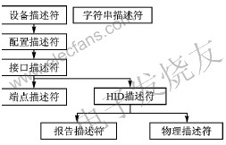
Figure 1 Relationship between various descriptors of HID
As can be seen from Figure 1, in addition to some descriptors defined by the USB standard, HID devices must also define HID descriptors. In addition, the communication between the device and the host is realized in the form of a report, so a report descriptor must also be defined; a physical descriptor is not necessary. Also, the HID descriptor is associated with the interface (not the endpoint), so the device does not need to provide a HID descriptor for each endpoint.
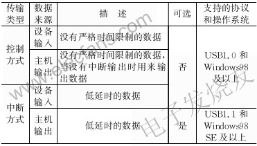
There are 4 transmission methods for USB devices to communicate with the host: control mode, interrupt mode, batch mode and synchronization mode. Each method has its field of application. HID only supports control and interrupt transmission methods. As shown in Figure 2, the HID device must have a default control pipeline and an interrupt input endpoint; the interrupt output endpoint is optional.
Figure 2 HID class equipment use control and interrupt transmission mode
Interrupt output transmission is the content of the USB1.1 specification, and must be supported by the Windows system. The interrupt output transmission method is only supported from the Windows98 SE version, so if you need to interrupt the output transmission method, the device should choose the corresponding operating system. Table 1 lists the transmission types and related conditions.
Table 1 Transmission methods supported by HID devices
The USB protocol defines 11 kinds of request commands, through which to obtain the information of the device and set the device. In addition to supporting these 11 standard requests, HID devices must also implement the following 6 specific requests:
①Get_Report——The host uses control transmission to receive data from the device, and all HID devices must support this request;
② Set_Report——The device uses control transmission to receive data from the host, the device may not support this request;
③ Get_Idle——The host reads the current idle rate of the device, the device may not support this request;
④ Set_Idle——Set the idle state, the device may not support this request;
⑤ Get_Protocol——The host obtains whether the current activity of the device is the boot protocol or the report protocol;
⑥ Set_Protocol——Switch between boot protocol and report protocol. If the device supports system boot (such as keyboard and mouse), it must support Get_Protocol and Set_Protocol requests.
2 HID interface firmware design and implementation
The device is implemented using C8051F120 microcontroller and PDIUSBD12 chip, as shown in Figure 3.
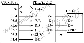
Figure 3 HID system structure block diagram
Because the main endpoint (Endpoint2) of PDIUSBD12 has 64 bytes of double buffering, which can provide a relatively high speed, it is configured as an interrupt transfer method in the endpoint descriptor, and Endpoint1 is not used. PDIUSBD12 triggers the CPU through interrupts to respond to various requests from the host.
The USB protocol version adopted by this system is 1.1, so it can support interrupt output transmission. In order for the host to recognize the device as a HID category, the value of the category field must be set to 0x03 (HID category) when defining the device interface descriptor, so that the host will continue to request the device's HID descriptor and report descriptor. In the host Get_Descriptor request, when the high byte of the value field is 0x21, it indicates that the host requires the HID descriptor; when the high byte of the value field is 0x22, the host requests the report descriptor. For the report descriptor, you can refer to the HID Usage Tables specification. The HID Descriptor Tool tool can help create and test written report descriptors. This defines a report descriptor for input and output 64-byte data.
code unsigned char szReport [] = {
0x06,0xA0,0xFF, // Usage page (FFA0h, vendor defined)
0x09, 0x01, // Usage (vendor defined)
0xA1, 0x01, // Collection (ApplicaTIon)
0x09, 0x02, // Usage (vendor defined)
0xA1, 0x00, // Collection (Physical)
0x06,0xA1,0xFF, // Usage page (vendor defined)
// Enter report
0x09, 0x03, // Usage (vendor defined)
0x09, 0x04, // Usage (vendor defined)
0x15, 0x80, // logical minimum (0x80 or -128)
0x25, 0x7F, // logical maximum (0x7F or 127)
0x35, 0x00, // Physical minimum (0)
0x45, 0xFF, // physical maximum (255)
0x75, 0x08, // Report length Report size (8 bits)
0x95, 0x40, // Report value (64 fields)
0x81, 0x02, // input (data, variable, absolute)
// Output report
0x09, 0x05, // Usage (vendor defined)
0x09, 0x06, // Usage (vendor defined)
0x15, 0x80, // logical minimum (0x80 or -128)
0x25, 0x7F, // logical maximum (0x7F or 127)
0x35, 0x00, // Physical minimum (0)
0x45, 0xFF, // physical maximum (255)
0x75, 0x08, // report length (8 bits)
0x95, 0x40, // Report value (64 fields)
0x91, 0x02, // output (data, variable, absolute)
0xC0, // End of collection (Physical)
0xC0 // end of collection (ApplicaTIon)
};
In this way, the input and output of the following data must meet the format of the report before they can be transmitted.
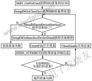
Figure 4 Application process enumerating HID devices
3 Application design and implementation
Windows provides powerful support for applications to access HID devices, and there is a full set of APIs for accessing HID devices. To access a device, an application must first enumerate to the device. Figure 4 shows the process for the application to enumerate HID devices.
After the enumeration is successful, you can use ReadFile and WriteFile to read and write device data based on the returned device handle. Here, the data is read and written in an asynchronous manner, so that no blocking occurs during reading and writing, which improves the efficiency of the program. The following are the main points of reading and writing devices asynchronously:
â‘ In order to achieve asynchronous access to the device, the FILE_FLAG_OVERLAPPED flag must be used when the CreateFile opens the device.
â‘¡ After successfully opening the device, use CreateThread to create a thread for reading the device.
â‘¢ First create an OVERLAPPED structure in this thread, and initialize its hEvent member with the CreateEvent function, so that an event object is created.
â‘£ Call the ReadFile function and pass in this structure.
⑤ It will return immediately after calling ReadFile. You must call GetLast? Error to get the error code. If it is ERROR_IO_PENDING, it means that the operation is waiting for completion; otherwise, it means that the call is wrong.
â‘¥ Call WaitForSingleObject to wait for the notification of hEvent event and make this thread go to sleep. If data is sent to the host, the reader thread will be activated.
The use of WriteFile also requires asynchronous operations, similar to the use of ReadFile.
It should be noted here that each time you read and write data, you must first receive and send a 1-byte PID flag, so each time you read and write data, you must add one byte. For example, here every time you read and write 64 bytes of data, but you must put 1 byte of PID data before the 64 bytes, so it is 65 bytes. Generally, the value of this byte is 0.
4 Summary
After making full use of the double-buffering feature of the PDIUSBD12 main port, the transmission speed between the test equipment and the PC can reach more than 8 KB / s. For some transmission data, the amount of data is not large, the speed requirement is not high, and it must respond in a short time The occasion can basically meet the requirements. On this basis, as long as different report descriptors are generated, a variety of different embedded devices can be developed; and such devices do not require drivers, and can start working immediately after plugging in the PC, eliminating the process of installing drivers, easy to use.
Emphasis: Because of the market chaos and the cheating of bad dealers, most people simply don't understand USB 3.0 and USB 3.1. USB 3.1 Gen1 is USB 3.0. And USB 3.1 Gen2 is the real USB 3.1. The maximum transmission bandwidth of USB 2.0 is 480 Mbps (i.e. 60MB/s), USB 3.0 (i.e. USB 3.1 Gen1) is 5.0 Gbps (500MB/s), and USB 3.1 Gen 2 is 10.0 Gbps (although the nominal interface theoretical rate of USB 3.1 is 10Gbps), but it also retains some bandwidth to support other functions, so it has a good performance. The actual effective bandwidth is about 7.2 Gbps. USB 2.0 is a four-pin interface, and USB 3.0 and USB 3.1 are nine-pin interfaces.
USB 3.1 is the latest USB specification, which was initiated by big companies such as Intel. Compared with the existing USB technology, the new USB technology uses a more efficient data encoding system and provides more than twice the effective data throughput (USB IF Association). It is fully downward compatible with existing USB connectors and cables.
USB 3.1 is compatible with existing USB 3.0 software stacks and devices
USB3.1 LOGO
USB3.1 LOGO
Protocol, 5Gbps hubs and devices, USB 2.0 products.
Intel, which owns Thunderbolt technology, also welcomes the formation of the USB 3.1 standard. USB 3.1 contains most of the features of USB 3.0 [2]. USB 3.1, as the next generation of USB transmission specifications, is commonly referred to as "SuperSpeed+", which will replace USB 3.0 in the future. [3]
USB 3.1 C SMT FINISHED,DIP USB3.1 Plug,Vertical USB Connector,USB Type-c Receptacles Shell
ShenZhen Antenk Electronics Co,Ltd , https://www.pcbsocket.com