As shown in Figures 1a and 1b, the synchronous buck converter IC can be used in an inverted buck-boost configuration by simply modifying the buck converter schematic. The inverting buck-boost converter generates the negative output voltage as follows: VOUT= -D/(1-D) x VIN
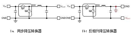
Figure 1. Using a Buck Regulator IC as an Inverting Buck-Boost Converter
The operation of the inverting buck-boost converter is shown in Figures 2a and 2b. During TON (Q1: turn-on; Q2: turn-off), the inductor stores energy; while during TOFF (Q1: off; Q2: turn-on), the inductor charges the output capacitor.
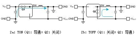
Figure 2. Reversed buck-boost operation
Inverted buck-boost configuration of the falling voltage IC's maximum VIN and IOUT
When using a buck regulator IC in an inverting configuration, you need to reduce the converter's maximum input voltage and maximum output current range. We illustrate these concepts using the LM5017-based inverting buck-boost circuit in Figure 3. In this configuration, the IC's bias ground (RTN pin) is connected to the negative output voltage (-10V). The input (VIN) and return (RTN) voltages of the IC are:
VIN, RTN = VIN + |VOUT|
Therefore, the maximum input voltage is: VIN(MAX) = VIN,RTN (MAX) - |VOUT|
Since the inductor current only supplies the output capacitor during TOFF (Figure 2b), the output current is: IOUT = IL1 (1-D)
Where D is the duty cycle. The maximum output current is related to the switch current limit, as shown in the following equation:
iL1(peak) = iSW(peak) = IL1+ΔIL1/2 = IOUT/(1-D) + ΔIL1/2
Where ΔIL1 is the peak-to-peak inductor current ripple that peaks at maximum VIN(MAX):
Figure 3 is a circuit diagram of the complete RP buck converter based on the LM5017. Due to its wide VIN (100V) rating, the LM5017 can operate over a wide input voltage rail in reverse phase buck-boost applications.
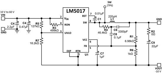
Figure 3. 10V~60V Input to -10V Output, 300mA Inverting Buck-Boost Application Circuit
See the original text : http://
The Texas Instruments online technical support community provides technical support for Chinese electronics engineers to answer technical challenges. The German instrument community involves analog electronic technology, microcontroller, MCU, embedded system, DSP, digital signal processing, and is the preferred technology exchange platform for electronic engineers using TI chip design. For more forums, please visit: http://
Substation Transformer,Prefabricated Substation,High Quality Prefabricated Substation,European Type Substation
Hangzhou Qiantang River Electric Group Co., Ltd.(QRE) , https://www.qretransformer.com