Wang Wei, Cui Fang, Liu Chi, Liang Lijun, Zhang Dongliang, Chongqing University of Posts and Telecommunications
Key words: IEC61850; Interval protection; PowerPC 8247; Real-time task; Inter-task communication
introduction
The IEC 61850 standard lays a foundation for the standardization of digital substations. The main function of the substation automation system is to achieve self-protection of the device. Domestic exploration and application of IEC 61850 did not begin with protection devices. The main consideration was the complexity, diversity, and configuration flexibility of the protection functions, which made it difficult to model the protection function fully compliant with IEC 61850.
The standard interoperability and free distribution of features require that different intelligent electronic devices (IEDs) in substation automation systems be able to collaborate more flexibly. Based on the in-depth study of the IEC 61850 standard for modeling the protection function, this paper proposes a digital substation transition scheme that is suitable for the structure and operation mode of the domestic power grid, based on the current situation of the development and application of domestic protection devices. Space protection system design method.
1 Digital substation transition plan
At present, the use of intelligent primary equipment (such as electronic transformers and intelligent switches, etc.), networked secondary equipment, and an IEC 61850 communication specification and automated operation management system are the main technical features of digital substations. Figure 1 shows the digital substation system structure.
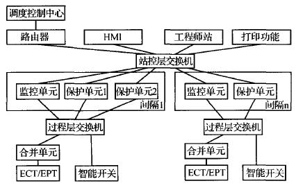
Figure 1 Digital Substation System Structure
In view of the fact that China's research and practice of IEC 61850 standard is still at an exploratory stage, the maturity of domestic electronic transformer technology is still to be assessed, and the implementation of IEC 61850 in the process and interval layers of substations should be implemented step by step. Aiming at this situation, a current digital substation system transition plan is proposed, as shown in Figure 2.
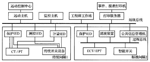
Figure 2 Interchange solution of several Yuhua substation systems
The process layer in the program adopts ECT/EPT and intelligent switches on the one hand, and the analog quantity acquisition and switch quantity control are fully digitalized. The real-time electrical quantity detection of power running, on-line monitoring and statistics of operating equipment status parameters, and execution of operation control are completed. Drive; On the other hand, it also supports the traditional hard wiring mode under the primary equipment, using the connecting wires to access conventional transformers and switches. The merging unit collects the real-time data information of the current interval and transmits the interval layer protection device via the process bus in a multicast manner so that the separation layer implements the protection control function for the primary device and prioritizes the data collection, statistical operations, and the issuance of control commands. In addition, the conventional transformer and switch data can also be obtained through the sampling board in the traditional mode. The substation layer adopts a digital substation station control layer system conforming to the IEC 61850 standard and is designed for a distributed system. Considering the ability of the 61850 device to access the network, the background uses the C/S mode and the workstation needs to retrieve data from the main server.
This scheme realizes the digitization of the spacer layer and the substation layer on the basis of the two-tier structure of the traditional substation. The data acquisition part of the traditional protection device includes analog (current, voltage) data conversion, read-in quantity (such as breaker position, auxiliary contact of isolation barrier), but data mapping method is used to accept: A/ The D conversion module is mapped as part of the IEC 61850 process level digital sensor; the switch output module is mapped as part of the IEC 61850 process level digital actuator; the switch input module is mapped as part of the IEC 61850 process level digital circuit breaker; The main control modules of the filtering, calculation, logic and control functions are mapped into the protection and control equipment of the IEC 61850 bay level.
With this mapping method, the protection device can directly receive the digital quantity while receiving the channel analog quantity. In other words, the device can well implement the function of the process layer and the bay layer in the IEC 61850 system, and can also take into account the existing system, thereby achieving a good coexistence and transition between conventional devices and secondary devices based on IEC 61850.
2 Hardware Design of Spacer Protection Device
2.1 Hardware Structure
Taking into account the above mapping method, the spacer protection device should be composed of an analog input module, a digital input module, a digital output module, a main controller, a liquid crystal display, and a power supply module. Each module is installed on the main board in the form of a plug-in, which can be freely increased or decreased according to the needs of users. The hardware structure diagram is shown in Figure 3.
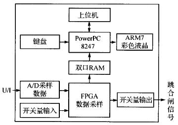
Figure 3 Schematic diagram of the hardware structure of the spacer protection device
According to the hardware structure diagram, the PowerPC platform has communication connections and data interactions with the upper computer, the dual port RAM of the FPGA, and the ARM7 color LCD.
2.2 Hardware Features
The main control board selected the PowerPC 8247 processor. Using its powerful computing processing capabilities, the VxWorks platform realized the configuration information analysis, data mapping, platform protection, data communication and other functions. The external SST39VF040 BIOS chip is used to store the Boot ROM program. 32 MB of Flash/R0M is used to store Vxworks programs, drivers, configuration file information, and storage data. 32 MB x 4 RAM is used to store system and application running programs, real-time configuration information, real-time data, etc. 100M full-duplex Ethernet port is used for real-time communication, RS232 is used to connect the printer, and RS485 is used to connect the LCD panel.
3 Protection Device Implementation Platform Software Design
The traditional relay protection generally adopts the linear programming of the one-chip computer, namely the development method of front and back system. The application program runs from the background, generally an infinite loop. The corresponding function (or subroutine) is called in the loop to complete the corresponding operation (called background behavior or task level), and the interrupt is used to process random events (called foreground behavior or interrupts). level). In practical applications, the execution frequency of various foreground activities is inconsistent, such as the input sampling frequency may be very demanding, and the keyboard scanning is much less. In the case of a complicated system, some tasks may not be timely carried out. In addition, once the program is established, the execution of various foreground activities is fixed. If you need to dynamically change the execution structure at runtime, the program will need to add a lot of conditional judgments or branching, which increases the complexity, readability, and maintenance difficulty of the program. Therefore, when designing protection software conforming to IEC 61850, an embedded real-time operating system (RTOS) must be introduced.
The RTOS used in this paper is the Vxworks operating system. It has good continuous development capabilities, high-performance cores, and a friendly user development environment. It is widely used in communications, military, and aviation because of its good reliability and excellent real-time performance. High-precision technologies such as aerospace and high-precision real-time requirements. Compared with other operating systems, the robustness, real-time nature, and richness of components of Vxworks are undoubtedly very suitable for the development of this project. The application practice has also proved this point. This section describes the Vxworks-based protection device system platform design.
3.1 System Module Division
PowerPC software module structure shown in Figure 4.
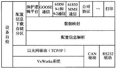
Figure 4 PowerPC software module structure
Bottom driver module: Implements CAN bus, RS232, Ethernet driver. Interface calls send and receive data.
Device self-checking module: whether the insertion board, switch board and analog board of the testing device are inserted. After being detected by the FPGA, it is judged by the first word of the dual-port RAM. The low 8 bits indicate the switchboard, and the high 8 bits indicate the analog quantity. board.
Configuration information download and storage partition: partition the storage space reasonably, receive and store different configuration information and forwarding configuration information (interface ARM7). Allocate storage address space (Flash) for storing data (fixed value, event, recorded wave).
The parsing module of configuration information: Creates all configuration information entities and reads the corresponding configuration information (from the configuration file) to provide a real-time call interface for the application program.
Data mapping module: According to the data mapping information, the configuration information and the actual operation data are linked together to form a complete data information structure, and the application program is invoked in real time. Map the storage address (Flash) of the stored data (fixed value, event, recorded wave). The data mapping module contains numerous message queues (using VxWorks management message queues) to enable interaction between protection logic and other communication platforms.
The configuration information analysis module: classifies and stores all the received configuration information, and transmits the required configuration information to each chip.
Protection logic platform: including analog acquisition, analysis of protection configuration, operation of protection elements, digital logic, wave recording module, and event generation module. 61850 and MMS communication module: Runs 61850 service, parses the configuration information of the node, and returns mapping data and configuration information according to the mapping standard.
Communication protocol encapsulation module: running communication protocol program (except 61850 communication protocol, such as company protocol), according to different physical connections and driving external connection communication.
According to the system structure and module level, it can be seen that the protection system has the following functions: data acquisition function, network communication function, protection platform function, protection operation function, wave recording function, debugging function, human-machine interface function, measurement function and self-test function .
3.2 Real-time task priority design
According to the function of the device, the system real-time tasks were designed, including control logic tasks, protection logic tasks, communication tasks, data collection tasks, and printing tasks.
The control logic task tControlLogic is the ultimate purpose of the protection device and is responsible for making protection actions based on the monitoring results. Once triggered, it will be executed immediately, sending a signal directly or tripping the breaker. So assign it the highest application task priority 100. It has three trigger modes: the amount of semaphores issued by the protection logic task, communication commands, or keyboard operations.
The protection logic task tProtectLogic is the basic function of the protection device and is also one of the trigger sources of the control logic, occupying the second priority 105. It is triggered by the data acquisition task, followed by a calculation and judgment process, and a trigger signal quantity is sent to other tasks such as digital output and display according to the judgment result.
Communication is a very important task for microcomputer protection devices. For unattended substations, it is the only way for monitoring personnel to obtain grid operation information. According to its importance and real-time requirements, should be set to a higher priority to ensure its response speed. Vxworks provides standard network socket (socket) interface, network programming is very convenient. Based on an in-depth understanding of the protocol communication process, two tasks were designed for communication management: tServe (priority is l10) is responsible for interception, acceptance, maintenance of socket connections, and real-time monitoring of communication status. Remote communication reliability; tProcess (priority level 111) is responsible for receiving, parsing, processing, and replying packets, and performs corresponding operations according to the command entry to realize telemetry, remote signaling, remote control, remote adjustment, fixed value calling, and fault recording wave calling. Other functions.
The real-time nature of data acquisition mapping is the guarantee of protection and timely action, so it must also have high priority. Create a task tDataMap (priority 112) to collect data from the dual-port RAM and perform data mapping in combination with configuration information to complete the data classification and identification, transfer, release the semaphore, and start other tasks.
The priority of the human-machine interaction task tHMInteraction is lower than that of the communication task and the data acquisition mapping task, which is set to 12O. It has 3 kinds of trigger sources: When the protection action, the protection task triggers the pop-up action information; keyboard operation triggers, view and modify the device parameters; timing trigger, perform once every other fixed time.
The fault recording function requires the recording to be reliable, never missed, and recorded well. It does not require high real-time performance. Its priority is defined as 140, which is lower than most tasks. After the data acquisition task obtains the real-time value, the message is transferred to the tRecord buffer of the fault recording recording task. At the same time, the semaphore is released to start the task. The tRcord task uses the mutation amount criteria to determine whether to start the recording. When the fault recording task is initialized, a large circular buffer needs to be established for storing real-time data. The buffer size should be appropriately configured according to the system memory usage. The waveform file is saved in the local Flash file system in the COMTRADE format, and is available for background retrieval when idle.
The self-test is an essential function of the microprocessor protection device. When the CPU is idle, it should be checked whether the various parts of the device are operating normally. In fact, many functions of the device need to be performed cyclically, such as watchdog maintenance, meter reading, and device timing. Therefore, a loop execution task is created, and it initiates a self-test task, which is automatically ended after the self-test is completed.
The print job has the lowest priority and is triggered by the keyboard when it needs to print.
The execution time of other parts is very short and does not affect the running of the task. Therefore, it is completed in the function call form without creating a task execution.
3.3 Inter-task Communication
The communication between various tasks mainly occurs between the protection platform tasks and the 61850 service, production equipment company agreement, and printing tasks. The configuration information receiving task is independent of other tasks and does not require interaction data. There are two ways of communication and data exchange between tasks: shared data area and message queue.
3.3.1 Shared Data Area
According to different data types, they divide the shared data area, such as analog data area, switch data area, vector data area, and so on. Each shared data area is divided into four parts: collection area, GOOSE data area, 61850 9-1 data area, and 61850 9-2 data area.
The protection platform stores analog or switch type data information collected by the device to the collection area. Data from other devices is obtained from the GOOSE data area, 61850 9-1 data area, and 61850 9-2 data area.
The GOOSE communication module transmits the information of the collection area to other devices via the GOOSE protocol, and stores the received GOOSE data in the GOOSE area.
The 61850 9-1 communication module transmits the information of the collection area to other devices through the 61850 9-1 protocol, and stores the received 9-1 type data to the 61850 9-1 area.
The 61850 9-2 communication module transmits the information of the collection area to other networks through the 61850 9-2 protocol, and stores the received 9-2 type data to the 61850 9-2 area.
3.3.2 Message Queue
According to the communication requirements between tasks, a total of 4 message queues are defined: event queue, recording queue, operation queue, and print queue. The event queue and the wave record queue are the protection platform sending messages to the queue, the 61850 service, and the device company protocol to get messages from such queues; the data flow of the control queues is the opposite, the 61850 service and device company protocols send messages to the queue to protect The platform obtains messages from the queue; the print queue protects the platform and the company protocol sends messages to the queue, and the print job gets messages from the queue.
Conclusion
The proposal of the smart grid will inevitably promote the rapid development and realization of digital substations. In this process, the IEC 61850 standard will be fully realized at the brother level of the substation. In this article, good software design with high reliability, high stability, and strong real-time performance and hardware design that meets the domestic development status provide a smooth transition between traditional substations and digital substations, promotes the flexibility and standardization of product programming development methods, and improves product interaction. Transmutation provides a solution. After actual testing, the device products meet the operational requirements and have been put on the market after further testing and optimization.
Remoter Controller,Remote Control,Wireless Remote, Universal Remote Control,universal remote
NINGBO COWELL ELECTRONICS & TECHNOLOGY CO., LTD , https://www.cowellsocket.com