The challenge for companies dedicated to the development of medical diagnostic equipment is to provide consumers with high-quality and inexpensive products. In reducing medical care costs and improving patient care services, the most important thing is to be able to reduce the size and accuracy of these medical devices. Today, with the aging population problem becoming more and more serious, the above-mentioned needs are more urgent. According to the InMedica report of the IMS survey company, total sales of consumer medical devices are expected to exceed US $ 5 billion by 2011.
With the development and continuous improvement of the monitoring function of medical equipment, remote care providers can provide better diagnostic tools for home patients, emergency room ambulancemen and even hospitals in several important areas of human health. Blood pressure monitors, blood glucose meters, defibrillators and other monitoring instruments require clear analog signals for accurate measurements, otherwise they may be life-threatening. Designing an excellent analog signal path can help designers reduce interference from extraneous noise, extend dynamic range, and enhance accuracy. In addition, in terms of component selection, designers must also choose carefully to meet the performance requirements of the final product.
High performance requirements in small packages
Previously, people generally thought that medical equipment in hospitals and clinics was more accurate than portable instruments used in homes. However, new technological trends are rapidly reversing the above-mentioned views. The users of the new portable medical equipment are not only ordinary consumers, but also patients with profound scientific and technological understanding, so the needs of customers are no longer limited to measuring body temperature, doing electrocardiogram and measuring blood pressure. What customers need is a full range of nursing and measurement functions.
In order to meet people's urgent needs for home medical diagnostic equipment, equipment suppliers are relying on advanced inventory management and innovative design to enhance market competitiveness and equip products with more functions to win more users. In the field of developing home medical instruments, a factor is very important, which is the development time required from the initial design of the product to the actual launch on the market. Shortening the time to market can allow manufacturers' products to seize the market. Whether the development cycle can be shortened depends on whether the system designer's design is flexible and cost-effective.
Process technology affects system design
Although electrical specifications are the main factor for designers to choose components, the process used to manufacture integrated circuits is equally important. For example, a typical blood glucose meter usually requires an operational amplifier with a very low input bias current. Most designers will choose a JFET amplifier. However, they should consider the temperature issue before making a decision.
Because the JFET has a very low initial input bias, it is very susceptible to temperature changes. For every 10 ° C rise in input, the input bias will approximately double. To calculate the drift of the input offset, the following formula (reference 1) can be used.
Ib (T) Ib (T0) x 2 (T-T0) / 10
For example, a JFET input operational amplifier (such as National Semiconductor ’s LF411) has an input bias current of 50pA at 25 ° C, and a better choice is National Semiconductor ’s LMP7731, which is a bipolar input operational amplifier , Its input bias current is 1.5nA. Through the above formula, we can quickly calculate that the input bias current of LF411 becomes 3.2nA at 85 ° C, which is twice that of LMP7731.
Evaluation system trade-offs
Speed, noise, and power consumption may be equally important for some designs. A low-noise device consumes more current, while a low-power device can only provide limited bandwidth. One way to overcome these problems is to use inverse compensation amplifiers in appropriate applications. Compared with the stability of unity gain and higher speed, the advantage of anti-compensation amplifier is that it can provide a larger bandwidth without affecting power consumption.
The anti-compensation operational amplifier is most suitable for use in current-voltage conversion (transimpedance) circuits. Among medical instruments, one of the most common applications is to measure the oxygen content in blood cells, called SPO2 or saturated or peripheral oxygen. Figure 1 shows the block diagram of the SPO2 module, in which the inverse compensation amplifier (TIA) is used to convert the current from the photodiode into a voltage.
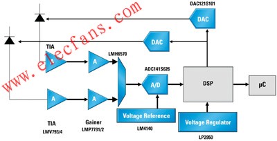
Figure 1 Typical block diagram of SPO2 module
Shortcut design time with shortcuts
The most important parameter of medical instruments is noise, which can cause serious interference between the circuit itself and nearby equipment. Calculating noise is a dull job, especially when you want to calculate the overall impact of the signal path on the signal-to-noise ratio from power supplies, amplifiers, data converters to external components.
In general, medical instrument circuits tend to work at lower frequencies, so designers of these systems usually care about noise in the 0.1 to 10 Hz band, also known as peak-to-peak noise. Unfortunately, some data sheets do not provide time-domain noise (peak-to-peak) values, but only provide typical graphs of voltage or current noise density. In addition to waiting for the supplier of the circuit to provide measurement data, there is a quick way to help calculate the peak-to-peak noise amount.
Suppose you plan to use National Semiconductor ’s LMP7731 to estimate the peak-to-peak (0.1 to 10 Hz) voltage noise amount. First, select a point within the frequency range of the specified frequency band, for example, 1 Hz, then the value when comparing curves Is 5.1nV / √Hz (Figure 2), then use the following formula to calculate the root mean square value (RMS) of the noise: Equation 1: enrms = "enf" √ln (10 / 0.1), where enf is at 1Hz The noise can be obtained from the above formula by 10.9nV total root mean square noise. To calculate the peak-to-peak noise, simply multiply this root mean square value by 6.6, so that 72.2nV can be obtained. The result of this estimation is quite good, it is very close to the specification of 78nV listed in the data sheet.
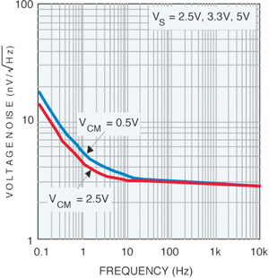
Figure 2 Relationship between input voltage noise and frequency of LMP7731 Frequency, voltage noise
If the voltage noise density graph in the data table does not show the noise value at 1 Hz, then you can use the following simple equation (Equation 2) to calculate the value at a certain frequency.
Formula 2: en = enb * √ (fce / f)
Where enb is broadband noise (usually the value at 1kHz), and fce is the 1 / f inflection point, and f is the frequency of interest, in our case it is 1Hz.
As an example, the broadband noise of National Semiconductor ’s LMV851 at 10kHz is 10nV / √Hz. In order to calculate the root mean square value noise, we must first determine the value of the 1 / f inflection point (fce) from the graph. Use the voltage noise density graph in the data sheet so that you can find that fce is approximately equal to 300 Hz. After that, using the above formula can calculate en = 10 * √ (300/1) = 173nV√Hz, and this is the voltage noise at 1Hz, and finally substitute this value into formula 1 and multiply the result by 6.6 , You can get the peak-to-peak noise of 2.4μV.
Another consideration is current noise. Generally speaking, if the impedance of the power supply is not very large (> 100kΩ), you can still get a very close estimation result without considering the current noise, just like the above example. However, if the impedance of the power supply is very large, it is necessary to use the same technique to estimate the current noise, and add the voltage and current noise in the form of root mean square values.
Determining speed requirements
Just as the noise of an op amp is extremely important to the resolution of an ADC, so is the bandwidth to maintain the accuracy of the system. To limit the error to 1/2 least significant bit (LSB), a quick check is needed to determine whether the bandwidth of the amplifier is sufficient. In addition to using complex and general-purpose guidance, you can also use the resolution of the analog / digital converter to quickly calculate the results. The method is to use 1/2 (N / 2) and multiply the result by the amplifier frequency at -3dB (reference 2).
Through the above shortcut and a 14-bit ADC, this example yields feff = 0.007813 * f-3dB. For the operational amplifier (LMP7711) with a configurable gain of 10 in Figure 3, the frequency at -3dB is 1.7MHz. In this way, the maximum bandwidth (at 1/2 LSB error) is equal to 0.007813 * 1.7E6 = 13.3kHz.
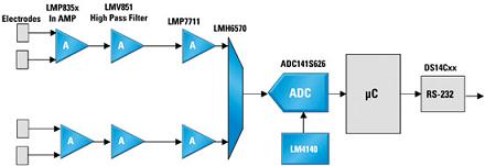
Figure 3 Block diagram of a portable electrocardiograph
Monitor device and communication device
Most newer medical diagnostic instruments have wireless communication capabilities. Modern electrocardiographs (EKG or ECG) can transfer patient data to a doctor's clinic or hospital within a few minutes through a personal electronic handbook (PDA) or other computer peripherals. Leaving aside the benefits of wireless data transmission, this type of equipment may cause serious interference to medical devices and cause incorrect readings.
In order to avoid such interference, a filter must be used. However, adding a filter will not only increase the size of the device, but also increase the cost of the design. A more cost-effective and fast method is to use components (including filters) that can suppress radio frequency (RF) noise.
Conclusion
The current trend in the field of medical equipment is to provide consumers with higher-value products, that is, inexpensive and high-quality home care equipment that can quickly provide diagnostic results. As technology continues to advance, more medical devices will transfer data from patients 'homes to doctors' clinics in real time via computers. In addition, as users demand more functions, the precision requirements for portable medical devices will be further improved to achieve more accurate diagnosis, and these will rely on designers' continuous innovation, long-term development and comprehensive solutions. committed to.
Outdoor led screen Kiosk as led poster is a very effective, eye-catching medium which can be fabricated as per the requirement of the application. A outdoor led poster or led screen kiosk in a standee with has an in-built player connected to the screens which can be updated from any remote location by using digital signage software. This medium can be used to welcome guests, advertise products as well as disseminate important information relevant to its viewers.
outdoor led screen Kiosk can have multiple led screens connected. The led screen poster can be used for advertisement but also the whether information and other tasks like online surfing, bill payments, shopping, etc for its users.
Outdoor Led Poster,Floor Standing Outdoor Led Poster,Outdoor Mobile Led Poster,Outdoor Led Flag Screen
Shenzhen Priva Tech Co., Ltd. , https://www.privaled.com