Keywords: AT89C51SND1C; ISP1362; U disk; MP3 player
The integrated design of the player and memory plays a key role in the portability of the MP3 player, but at the same time it brings many new problems. For example, the storage capacity is fixed. If you want to install more songs, you can only buy new products, which is a huge waste. On the other hand, integration has limited the use of MP3 players in other fields, such as automotive electronics. Therefore, separating the memory from the player becomes another development direction of the MP3, and is also the significance of developing this U disk MP3 player.
Main chip introduction
The AT89C51SND1 is an MP3 decoder chip based on the 8-bit C51 MCU core introduced by ATMEL. It has built-in MP3 hardware decoder, supports 48kHz, 44.1kHz, 32kHz, 24kHz, 22.05kHz and 16kHz sampling frequency, with subwoofer, midrange, treble equalization control and low surround sound effect. It adapts to the programmable audio output interface of different DACs on the market and is compatible with PCM and I2S formats. Built-in 2304B RAM and 64KB Flash program space, allowing users to add complex functions. The MP3 and audio clocks as well as the USB clock are provided via a built-in phase-locked loop.
To read a USB flash drive, a USB host controller is essential. In order to further upgrade the system in the future, this paper chose the powerful USB-OTG chip ISP1362. The ISP1362 integrates an OTG controller, an advanced host controller and a peripheral controller on a single chip. The ISP1362's OTG controller is fully compatible with USB 2.0 and On-The-Go Supplement 1. 0 protocol. The host and device controllers are compatible with the USB 2.0 protocol and support 12Mbps full speed transmission and 1.5Mbps low speed transmission. 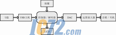
Figure 1 system frame diagram
System hardware structure
The whole system is built around AT89C51SND1, as shown in Figure 1. Since it has a hardware decoder inside, the circuit configuration is not complicated. First, the ISP 1362 is controlled by the single chip microcomputer, and the MP3 file in the U disk is read out and sent to the hardware decoder for decoding. After decoding, the digital signal is transmitted by the digital audio interface to the audio DAC CS4330, which is then converted to produce an audio signal. Since the signal power of the DAC output is limited, an operational amplifier is added to the back end, and the amplified signal can be directly output to a device such as a speaker or a headphone.
The AT89C51SND1 is a 51-core based microcontroller, so the minimum system structure is very simple. In addition to the crystal oscillator and reset circuit of the traditional single-chip microcomputer, there are PLL filter circuit and USB interface circuit, as shown in Figure 2.
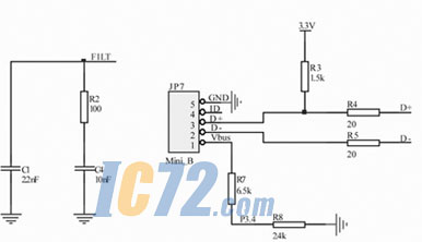
Figure 2 PLL filter circuit and USB interface circuit
ISP1362 is a 16-bit bus structure that cannot be directly interfaced with an 8-bit microcontroller. Therefore, the P0 and P2 ports of the MCU are connected to the 16-bit bus of the ISP1362 as the data bus, and are respectively connected to P3.4, P3.7 and P3.6 of the MCU, and controlled by the simulation read and write timing. Data reading and other operations.
In addition to these basic bus connections, the ISP1362 needs to be connected to some special control pins:
A0: used to determine whether the controller is in a command state or a data state: 0 indicates a data state, and 1 indicates a command state;
A1: Used to determine whether the controller works in the host or device control mode: 0 means in host control (HC) mode; 1 means in device control (DC) mode.
Connect to P1.5 of the MCU. When P1.5=0, it means that it is in the OTG working state, and P1.5=1 means it is in the non-OTG state.
INT1_USB and INT2_USB are connected to the INT0 and INT1 pins of the MCU to generate an interrupt.
The ISP1362 has two USB ports, an OTG port and a host port. Because the OTG port contains the host function, the system uses the OTG port to connect to the USB flash drive. According to the USB2.0 protocol, the USB host requires two 15k down TG ports and can be used as device ports, while the device has no pull-down resistors. Therefore, ISP1362 provides a "soft link" mechanism to control the connection of resistors through internal registers. Therefore, it is not necessary to add a pull-down resistor externally in the hardware design. For the open-drain output, a 10kW pull-up resistor R14_USB was added. As shown in Figure 3.

Figure 3 OTG port circuit diagram
Initialization of AT89C51SND1C and ISP1362
A series of initialization operations are required before starting to play MP3 files. These operations are done by setting the relevant registers inside the AT89C51SND1C and ISP1362.
Initialization of AT89C51SND1C
In order to play MP3 files normally, the following aspects must be set for the main controller AT89C51SND1C.
Phase-locked loop initialization
Both the MP3 decoder and the audio output interface use the clock provided by the internal phase-locked loop. The initialization of the phase-locked loop is accomplished by setting PLLCON, PLLNDIV, and PLLNDIV. The output frequency is calculated as: PLLclk = OSCclk × (R + 1) / (N + 1).
MP3 decoder initialization
The initialization of the MP3 decoder requires setting of MP3CON and MP3CLK. The MP3 decoder is divided into two types of interrupts, data interrupt and check interrupt, which can be set in MP3CON. Simple processing can use the query flag bit mode to avoid using interrupts. The MP3 decoder has certain requirements on the clock. The MP3 data in the MPEG I format requires a minimum clock of 21 MHz and an MPEG II format of 10.5 MHz. The clock is calculated as: MP3clk = PLLclk / (MPSD4: 0 + 1).
Audio output interface initialization
Before getting the two channels of serial data, you need to correctly set the relevant parts of AUDCON0 and AUDCON1 of the audio output interface. With the DAC chip CS4330, its settings are as follows: output 32-bit data format (DSIZ=1), the high level in the channel selection signal is the left channel (POL=1), select the data rate of 256·Fs (HLR=0 ), select the output of the MP3 decoder as the data source (SRC = 0), and the 18-bit data to the right (JUST4: 0 = 14). In order to hear the normal sound, you need to set MP3CLK according to the sampling rate of MP3 to get the correct audio output interface clock. The calculation formula of this clock is: AUDclk=PLLclk/(AUCD4:0+1).
Button initialization
In order to realize the human-computer interaction function of MP3, keyboard support is required. The AT89C51SND1C provides four interrupted button interfaces. When these interrupts are enabled, the status of the buttons can be obtained simply by reading KBSTA. When the button is initialized, it only needs to open the interrupt of the corresponding interface in KBCON, and then open the EA of the total interrupt.
ISP1362 settings
In order to correctly read MP3 files from the USB flash drive, the following aspects must be set for the USB control chip ISP1362.
Division of data buffer
The ISP1362 has a 4KB data buffer inside, which can be divided into 4 parts for use in the four USB transmission modes. The synchronous transmission is double buffered, occupying ISTL0 and ISTL1, and the size of the two is generally the same. Interrupt transfers occupy INTL. Control transmission and block transmission share ATL. The sizes of ISTL, INTL, and ATL are set by HcISTLBufferSize, HcINTLBufferSize, and HcATLBufferSize, respectively.
Interrupt setting
The interrupt here does not refer to interrupt transmission in USB, but to hardware interrupt in the traditional sense. If you do not use an interrupt, you should turn it off by setting HcuPInterruptEnable to 0 and all bits in HcInterruptDisable to 1.
ATL buffer setting
Control transfer is the type of data transfer that any USB device has. In ISP1362, it occupies the ATL buffer, so the ATL buffer setting is essential. The specific operation is to set the following registers: HcATLPTDSkipMap, HcATLLastPTD, HcATLBlkSize, HcATLPTDDoneThresholdCount, and HcATLPTDDoneThresholdTimeOut.
Other related registers
ISP1362 also has some hardware settings, such as port settings and overcurrent protection. In addition to this, you need to determine the maximum amount of data sent by a frame, etc. These operations are done by setting the HcHardwareConfiguration and HcFmInterval registers.
Read U disk
The U disk uses a block transfer method when using USB transfer, and the operation is relatively complicated. In addition to the most basic USB protocol, there are many other related protocols that need to be implemented, such as Mass Storage, Bulk-Only, SCSI-2, UFI, and so on. However, for the USB interface chip ISP1362, all that needs to be completed is the data transmission according to the protocol.
Related descriptors and settings
U disk generally communicates using the Mass Storage protocol. However, before using the Mass Storage protocol to communicate, you should first focus on the transport protocol and the endpoint descriptor of the USB flash drive.
The transport protocol in Mass Storage is commonly used for Bulk_Only. However, in this transmission mode, multiple instruction sets can be divided, and the U disk is commonly used in the SCSI command set. Bulk_Only transmission mode should first read the endpoint descriptor to obtain the two endpoint numbers Bulk_In and Bulk_Out, and then the normal communication of USB can be performed.
FAT file system
Since the capacity of the U disk is generally large, the operation of the U disk is often performed in blocks, and the size is generally 512B. However, the data on the actual U disk is stored in the file system. Currently, the file systems commonly used in U disk are FAT16 and FAT32. These two file systems are identical in many aspects. Therefore, in the actual access, they can be easily distinguished, and then different operations can be performed to access the U disk of different file systems. Sex.
Play MP3 files
Playing an MP3 file requires the following steps: parsing the file system of the U disk, obtaining the information of the MP3 file, reading the specified MP3 file from the U disk, and sending the data in the file to the MP3 decoder embedded in the AT89C51SND1C. The decoded data is formatted by the audio output interface to output serial data of two channels, and then the digital signal is converted into an analog signal by the DAC chip CS4330, and finally the signal is amplified and output through the integrated operational amplifier MC33202.
Initialize the relevant chip
The initialization of the master controller AT89C51SND1C and the USB interface chip ISP1362 is crucial. In addition to some of the above-mentioned initialization settings, it should be noted that the microcontroller and ISP1362 reset should be synchronized. In addition, the relevant registers of the MP3 decoder volume control should be initialized. By default, they are all 0, that is, they are muted.
Get the data in the MP3 file
Obtaining MP3 files from a USB flash drive is a relatively cumbersome process. First, you should be able to read the data of the specified block on the USB flash drive according to the USB protocol, and then parse the file system according to the obtained data to obtain the specified MP3 file. Start the block address, and then get the subsequent data by checking the FAT table. Also, the obtained data should be stored in the data cache opened inside the AT89C51SND1C, and used when the MP3 decoder lacks data. Since the data buffer inside the MP3 decoder is small, it is required to obtain MP3 file data as little as possible, which requires the code of this part to be as simple as possible.
MP3 decoder decoding
Before starting the MP3 decoder, the frame header of the read MP3 data should be parsed, and the clock of the audio output interface is set according to the parsed sampling rate. The data read from the U disk should also be temporarily stored in the data cache opened in the AT89C51SND1C. Before starting playback, you need to first send 1KB of data to the MP3 decoder's data buffer through MP3DAT, and then the MP3 decoder will have missing data. The status (MPFREQ=1 in the MP3STA1 register), and the data in the internal data buffer of the AT89C51SND1C is written into the MP3 decoder. When all the data in the data cache is used up, you should immediately read the U disk again, and so on until the entire MP3 file is played.
Conclusion
The system realizes the recognition and reading of the U disk well, breaking the limitation of the integration of the decoder and the memory in the traditional MP3 player, and only needs to use a larger capacity U disk to increase the storage on the original hardware. Capacity has a good application prospect in audio and automotive electronics.
references:
[1]. AT89C51SND1 datasheet http://
[2]. ISP1362 datasheet http://
[3]. AT89C51SND1C datasheet http://
[4]. MC33202 datasheet http://
:
LED Lawn Lamps China manufacturers
High purity aluminum housing, electrostatic powder paint with high corrosion resistance;
light source adopts Energy-saving lamps or high quality Led Bulb Lights, high efficient, long lifetime and good CRI,
LED Lawn Lamps suitable for illumination of urban squares, parks, communities, etc.

LED Lawn Lamps
Led Garden Lamp,Outdoor Garden Lamps,Led Street Lamp,Led Lawn Lamp
Changzhou Northern Lights Energy Technology Co.,Ltd. , http://www.lamps-china.com