The optimal design of wind turbine blades must meet certain design goals, some of which are even contradictory, such as:
Annual output power is maximized; maximum power is limited to output; vibration is minimized and resonance is avoided; material consumption is minimized; local and overall stability of the blade structure is guaranteed; blade structure meets appropriate strength requirements and stiffness requirements.
The design of wind power blades can be divided into two major stages: aerodynamic design and structural design. The aerodynamic design requirements must satisfy the first two goals. The structural design requirements must satisfy the last four goals. Usually these two stages are not performed independently, but an iterative process. The blade thickness must be sufficient to ensure that the web can be accommodated and the stiffness of the blade is increased.
(1) Shape design
Blade aerodynamic design is mainly shape optimization design, which is a crucial step in the design of the blade. The shape of the blade airfoil design in the shape optimization design directly determines the power generation efficiency of the fan. Under the fan operating conditions, the Reynolds number of the flow is relatively low, and the blade is usually operated under the state of low speed and high lift coefficient, and the flow interference between the blades causes flow. very complicated. Due to the complex flow state of the blade profile and the distribution of the blades from different azimuths of the blade profile, the design of the blade profile becomes very important. At present, the design technology of the blade airfoil generally adopts the advanced aeroplane wing wing airfoil design method to design the shape of the blade leaflet. The advanced CFD technology has been widely used in the design of different types of aerodynamic shapes. For the conditions of low Reynolds number and high lift coefficient, it is necessary to analyze the flow field of the blade airfoil by using the NS control equation with viscosity.
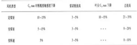
Over the past 10 years, horizontal-axis wind turbine blade airfoils have generally selected NACA series of airfoils, such as NACA44XX, NA-CA23XX, NACA63XX, and NASA LS(1). These airfoils are very sensitive to the roughness of the leading edge. Once the leading edge becomes rough due to contamination, the airfoil performance will be greatly reduced and the annual output power loss will be up to 30%. After recognizing that aviation airfoils are not suitable for wind turbine blades, after the mid-1980s, wind power developed countries began to study blade-specific airfoils, and successfully developed wind turbine blade-specific airfoil series, such as the US Seri and NREL series, and Denmark. RISO-A series, Sweden FFA-W series and Dutch DU series.
These airfoils have their own advantages. The Seri series is less sensitive to airfoil surface roughness; the RISO-A series has good stall performance at near stall and low sensitivity to front edge roughness; the FFA-W series has good after Stall performance. Danish LM company has adopted Swedish FFA-W airfoil on large-scale wind turbine blades. Fan-specific airfoils will be widely used in wind turbine blade design. Table 1 provides an estimate of the increased performance of the NREL airfoil series.
At present, there are several design theories of blade profile, which are developed based on the aerodynamic theory of the wing. The first shape design theory is a simplified design method according to the Bates theory. This method assumes that the wind turbine is operating in accordance with the best conditions of the Bates formula. The eddy current loss is not considered at all, and the efficiency of the designed wind wheel is not exceeded. 40%. Later, some famous pneumatic scientists successively established their own blade aerodynamic theory. The Schmitz theory takes into account the circumferential eddy current losses of the blades and the design results are relatively accurate. Glauert's theory considers the vortex flow after the wind wheel, but neglects the influence of the blade airfoil resistance and the slight loss of the blade, has less influence on the shape of the blade, and has greater influence on the efficiency of the wind wheel. Wilson made an improvement based on Glauert's theory, studied the effects of leaf loss and lift-drag ratio on the best performance of blades, and studied the performance of wind turbines under off-design conditions. It is currently the most commonly used design theory.
(2) Structural Design
At present, the structure of large-scale wind power blades is in the form of a skin main beam, as shown in Figure 1 as a typical blade structure. The skin is mainly reinforced by a biaxial composite material layer, providing aerodynamic shapes and bearing most of the shear load. The trailing edge has a wider cavity and uses a sandwich structure to increase its resistance to destabilization, which is similar to a large number of sandwich structures used in automobiles. The main beam is mainly reinforced by a unidirectional composite material layer and is the main bearing structure of the blade. The web is a sandwich structure that supports the main beam.
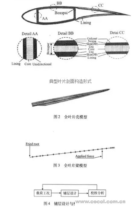
Typical blade section configuration
Structural lay-up check is also essential for blade structure design. In the former school nuclear field, mostly general-purpose commercial finite element software, such as ANSYS, NASTRAN, ABAQUS and so on. When checking the blades, consider the ultimate strength of the single layer, the natural frequency and the tip deflection, analyze the model shell model and beam model, and can achieve the mutual conversion of the two models, as shown in Figure 2, 3 Show. Compared with other blade structures, the hollow sandwich structure of large-sized blades currently has a high anti-buckling and destabilizing ability and a high natural frequency, so that the designed blades are relatively light. Finite element method can be used for design, but it is more used for analog analysis than design. Design and simulation must be cross-processed. After each step is completed, the analysis model must be updated to regain the stress and strain data in the laminate, and then return. Design, change the lamination scheme, and then analyze stress and deformation until the design criteria are met, as shown in Figure 4. Because of the particularity of the orthotropic composite material, the stress in each layer of the blade is not continuous, but the strain is relatively continuous. Therefore, the failure criterion of the blade structure verification sometimes completely adopts the strain failure criterion.
(3) Material selection
At the early stage of wind turbine blade development, due to the small size of the blades, there are wood blades, cloth skin blades, steel fiberglass skin blades, aluminum alloy blades, and so on. As the blades grow to larger sizes, composite materials gradually replace other materials and almost become The only material available for large blades. One of the advantages that composites have incomparable to other single materials is their designability. By adjusting the direction of the monolayer, the required strength and stiffness in that direction can be obtained. More importantly, the anisotropy of the material can be utilized to couple the different deformations of the structure. For example, due to the bending and torsion coupling, the structure twists when it is only subjected to a bending moment. In the past, the cross-section coupling effect of the blade was a difficult problem for designers, and the design project tried to eliminate the coupling phenomenon. However, in the field of aviation, people began to use the bending and torsion coupling of composite materials, and the coupling effect of tension and shear to improve the performance of the wing. On the blade, a bending and torsion coupling design concept is introduced to control the aeroelastic deformation of the blade, which is the aeroelastic cutting. Through aeroelastic cutting, the blade's fatigue load is reduced and the power output is optimized.
Fiberglass-reinforced plastic (FRP) is the most commonly used composite material for modern wind turbine blades. FRP dominates the dominant position of large-scale fan blade materials for its low price and excellent performance. However, as the blades become larger, the diameter of the wind turbine has exceeded 120m, the longest blade has achieved 61.5m, and the blade has a weight of 18t. This places more stringent requirements on the strength and stiffness of the material. All FRP blades have been unable to meet the requirements of large-sized and lightweight blades. Carbon fibers or other high-strength fibers are then applied to localized areas of the blade, such as NEG Micon NM 82.40m long blades, and LM61.5m long blades use carbon fiber in high stress areas. As the blades increase, stiffness becomes increasingly important and has become the key to the design of the new generation of MW blades.
The use of carbon fiber has greatly improved the stiffness of wind turbine blades and has not increased its own weight. Vestas uses carbon fiber for the 44m series blade main beams that are matched with the V903.OMW model. The blade has only 6t of its own weight, which is the same as that of the V802MW and 39m blades. Research reports in the United States and Europe indicate that carbon fiber-laden load-bearing glass fiber laminates are a very effective alternative to MW grade blades. In the EC-funded research program [10], it was pointed out that the use of carbon fiber in the 120m diameter rotor blade part can effectively reduce the overall weight by 38% and the design cost by 14%. However, carbon fibers are expensive and limit their use on fan blades.
Today, the carbon fiber industry is still focused on the development of lightweight, good structure and good thermal properties and other aeronautical application materials. However, many researchers have boldly predicted that the application of carbon fiber will gradually increase. The cost-effectiveness of wind energy will depend on the use of carbon fiber. To replace glass fiber in large quantities in the future, it must be low-priced to be competitive.
An electric slip ring is a rotary electrical connector. It allows uninterrupted power or signal transfer between two stationary points. It is also known as an electric Rotary Joint, power swivel, or electrical rotary joint. Electric slip rings are usually composed of a metal ring with several brush contacts on the inner circumference. And there are one or more pairs of contacts for power or signals on the outer circumference. The metal ring can be rigid or flexible, depending on the application.
An electric slip ring is an electromechanical device that allows the transmission of electrical power and signals from a stationary to a rotating structure. It consists of an electrically conductive rotating disc or ring, with a number of electrical contacts (or "slots") on its surface. The contacts are connected to external circuits, enabling the passage of power and/or data from the stationary to the rotating structure. Slip rings are also used in generators, where they allow the passage of current from the rotor to the stator.
A flat disc electrical slip ring is one kind of electric slip ring, it has many advantages: simple construction, small size, low cost, easy installation, and maintenance. It is widely used in various fields such as machine tools, textile machinery, printing machinery, packaging machinery, medical equipment, and aerospace equipment.
A 360-degree rotating Conductive Slip Ring is also called a hollow shaft slip ring or hollow conduct. It has an opening in the center that allows a shaft to pass through, making it ideal for rotating applications. Slip rings are often used in medical equipment, robotics, and manufacturing assemblies where rotation is required. This type of slip ring can handle large currents and voltages while providing a continuous electrical connection.
Electric Slip Ring,Slip Rings In Generator,Flat Disc Electrical Slip Ring,Slip Ring Electric Motor
Dongguan Oubaibo Technology Co., Ltd. , https://www.sliprob.com