In the train control system of the high-speed railway, CAN communication failures often occur due to the long communication distance, but the reasons and principles of the failures are completely unknown. What exactly is it like? Let's take a high-speed rail as an example for detailed explanation.
With the gradual improvement of people’s pace of life, the distance between regions is no longer a problem. This is due to the vigorous development of the transportation industry. Among them, high-speed rail, as a leader in the transportation industry, has also been widely used by the people. Recognized. Because of this, the communication problem in high-speed rail has also been highly valued by various equipment suppliers and railway companies. They cannot tolerate this kind of error, because it is closely related to the life safety of every traveler and train crew. The following is a brief example to explain a certain high-speed rail communication problem.
1. Causes of bus delay
The CAN bus mainly restricts its transmission distance. Due to the long body of the high-speed train with more communication points, it will cause delays in data transmission and response. There is a delay when the wire transmits data. Generally, the delay is 5ns/m. At the same time, different isolation devices will also cause different delays. Among them, it is also related to the wire material (0.2 square meters of gold-plated copper wire is equivalent to 1.0 square meters of copper wire), CAN transceivers and isolation methods, for example, the delay of optocoupler isolation is much larger than that of magnetic coupling isolation.
If CAN's resynchronization cannot compensate for the delay in transmission, the bit width of the response delimiter will become larger, and eventually the response delimiter will be recognized incorrectly during the recognition process, and the recessive level will be recognized as a dominant voltage. Ping, there is a delimiter error. As shown in Figure 1:
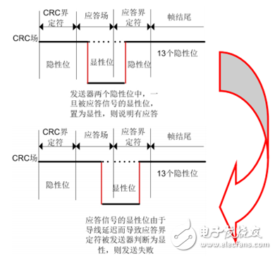
Chart 1 Delay error
Second, the result of the delay error
The following is an explanation of the types of delay errors that occur in a high-speed railway:
The types of errors detected this time mainly include: response delimiter error, delimiter format error, and frame end format error. They are all caused by delay errors. Take the following response delimiter error as an example:
u Response delimiter error
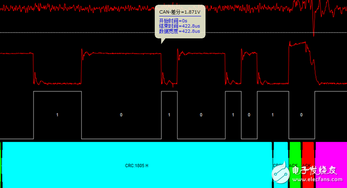
Chart 2 Response delimiter error
From the data, we can see that the response delimiter should be at a recessive level, but the response delimiter has always been in the dominant state due to the delay in transmitting the response, which leads to an error in the format of the response delimiter.
Three, how to detect transmission delay
First, if you want to detect CAN bus delay errors, you must have a corresponding CAN bus analyzer. The following is an example of the CANSCOPE detection method of Guangzhou Zhiyuan Electronics:
1) Delay analysis
In order to locate the fault point faster, we must first analyze the delay status of the entire communication process to find out where the delay exists. According to the "transmission delay" in CANSCOPE, the entire list is arranged in order of delay from largest to smallest, with 0.245 times the bit width as the boundary, beyond this range, it can be defined as a risk of response error.
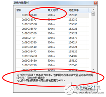
Chart 3 Delay statistics and equivalent wire length
Because the nodes connected to the bus are all different from the test points, the delays caused are different. In order to detect the maximum delay of the bus, we usually place the test points at the farthest ends of the bus. The object of the test is also the messages sent by the two nodes at the farthest ends of the bus.

Chart 4 Delay measurement
We can assume that the message is sent from the leftmost master, then the slave farthest from him is the rightmost, and the maximum delay is: the overall wire delay + the circuit delay of the farthest node (that is, the rightmost) ( Including isolation device and transceiver delay).
Fourth, the method to eliminate the delay error
In order to reduce the delay, increase the communication distance and reduce the communication error rate, we can take the following measures:
1. Use the magnetically isolated CTM1051 scheme to design the interface transceiver circuit;
2. Use thicker wires instead of thin wires, the standard is 1.5 cables (delay 5ns/m);
3. Use gold-plated or silver-plated cables;
4. Add CANBridge, a network bridge relay device, to extend the communication distance.
5. Using optical fiber transmission, such as the CANHUB-AF1S1 of Zhiyuan Electronics, the same baud rate can extend the communication distance by 1 times.
Five, summary
To ensure the normal CAN bus communication, we must first ensure that the CAN nodes are properly arranged, and that every message arriving at the node does not have delay errors. Secondly, a good analysis tool is also essential, which can not only help us accurately and quickly If the fault is found, we can also test the working conditions of our bus in various environments in a simulation mode.
Beam Splitter,Dichroic Beam Splitter,Optical Beam Splitter Cube,Beam Splitter Cube
Danyang Horse Optical Co., Ltd , https://www.dyhorseoptical.com