As the Type C USB connector becomes the new standard in the consumer space, USB is entering more solutions such as automotive infotainment systems. When designing the highest reliability, the USB port expansion in different locations in the car presents a unique challenge. Because of faults such as battery short-circuit, short-circuit, and electrostatic discharge (ESD) conditions, automotive USB applications present use cases that do not exist in other markets. As power flows through the host vehicle battery, they are affected by the high voltage and current spikes that occur during the intended operation. In addition, connecting the processor, USB hub, charge controller, and load switch to the downstream circuitry on the VBUS and data lines requires protection against battery short-circuit events.
This article refers to the address: http://
In order to prevent the USB battery from being short-circuited, the overvoltage protection circuit must be used to disconnect the system power when the voltage at the USB interface is above the overvoltage threshold. Overvoltage field-effect transistors (FETs) should have fast response times to disconnect system power as quickly as possible, protecting the upstream system-on-chip (SoC) from unwanted voltage and current spikes. In addition, the USB 2.0 specification requires the use of an overcurrent detection circuit to automatically limit the current in an overcurrent event. Internal switches prevent excess battery damage to upstream equipment, maintain 5V rail stability, and properly isolate faults.
In Part 1 of the two-part series; I explained the best way to protect the USB circuit from a short-circuit in the battery. In this blog post, I will extend the best way to optimize your car's USB battery short-circuit design.
As automotive manufacturers may change overall output current requirements throughout the project, protection solutions with adjustable current limiting provide system designers with more flexibility; allowing them to easily adjust the output current of the USB port without restrictions A new device. If you need to protect your sensitive electronics from battery shorts and support up to 2.4A, you may need a flexible battery-proof short-circuit chip.
The TPD3S716-Q1 can charge for USB battery charging 1.2 (BC1.2), C-type USB 5V / 1.5 A and dedicated up to 2.4A charging peripherals. The automotive USB 2.0 interface protector is a single-chip solution with battery short-circuit, short-circuit and ESD protection with an adjustable current-limit load switch. The current threshold for overcurrent protection can be adjusted by a ground (GND) external resistor RADJ on the IADJ pin, as shown in Figure 1.
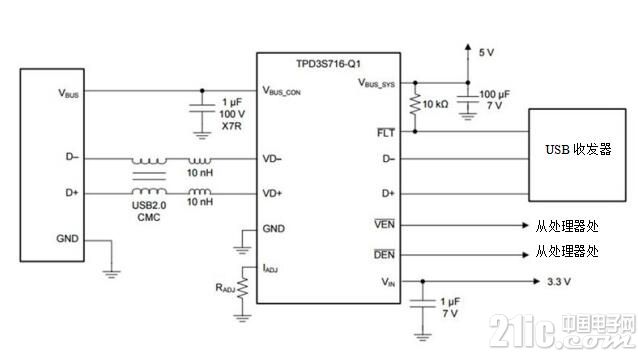
Figure 1: Typical application configuration for the TPD3S716-Q1
USB One-Click Copy (OTG) is another specification commonly used in automotive environments because it allows USB devices to switch between host and client roles. This feature is critical for USB high-speed applications where the head unit must be an extension of the mobile media experience. In order to achieve this goal, the head unit must be able to work in USB device mode accordingly.
The TPD3S716-Q1 has two enable inputs that can turn the internal FET of the device on/off. The VEN pin disables and enables the VBUS path, while the DEN pin disables and enables the data path. Independent control of VBUS and data paths allows you to configure this device for USB host and client/OTG mode, as shown in Table 1.
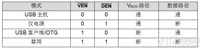
Table 1: Table of normal operation modes of equipment for TPD3S716-Q1
The easy access and small footprint to match the size range of the USB connector is an important consideration in USB high-speed protection solutions designed to facilitate layout and maintain signal integrity. The flow-through pin mapping allows the signal path to pass through the package, as shown in Figure 2.
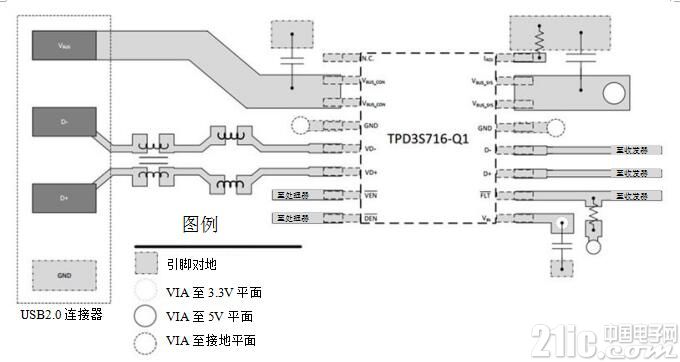
Figure 2: Example of a typical layout of the TPD3S716-Q1
Designed to prevent shorting of the USB battery, consider using a solution with adjustable current limit, OTG/client mode, and flow through routing. Doing so allows you to use additional features that are not currently present in other anti-battery short-circuit solutions.
Cable tray hangers are an essential component of a cable management system. They are designed to securely hold cable trays in place, providing a safe and organized environment for cables to run through. Cable tray hangers come in a variety of shapes and sizes, each designed to meet specific cable management needs.
Cable tray hangers are typically made from steel, aluminum, or stainless steel, and are available in different finishes, including galvanized, painted, or powder-coated. The choice of material and finish depends on the environment in which the cable tray hangers will be installed, as well as the weight and size of the cable trays they will be supporting.
One of the key benefits of cable tray hangers is their flexibility. They can be installed on walls, ceilings, or floors, and can be adjusted to accommodate different cable tray sizes and configurations. This makes them an ideal solution for a wide range of cable management applications, from data centers and server rooms to industrial facilities and commercial buildings.
Cable tray hangers are also designed to provide easy access to cables, making it simple to add or remove cables from the system. This is important for maintenance and repairs, as it allows technicians to quickly and easily access cables without disrupting the entire system.
Hangers of Cable Tray ,Cable Tray Brackets,Wire Cable Tray,Cable Tray Hangers
Rayhot Technology Group Co.,Ltd , https://www.cnrayhot.com