Radar, as an important military weaponry, compares its image to the "eyes" of combat commanders in the military and plays a decisive role in safeguarding national security and territorial integrity. However, with the development of digital circuit design and manufacturing technology, especially the advancement and improvement of CAD design software, a single test method such as ICT (In-Circuit Test) test, functional test, etc. can not meet the new radar digital circuit test and fault diagnosis. The requirements of the boundary scan [1] test will become the mainstream technology for the development of radar circuit digital circuit fault diagnosis in the future.
Based on the in-depth discussion of the limitations of ICT testing and functional testing, as well as the research and practice of boundary scan testing technology, this paper proposes the establishment of the "MERGE (combination)" boundary scan test model, and based on this method, builds a digital circuit. The portable automatic test system enables high-speed, accurate testing of new radar digital circuits. The system has the advantages of compact and portable hardware, stable and reliable performance, high fault isolation rate, and is suitable for real-time maintenance of battlefield level. It is an effective supplement for large-scale online testing and functional testing platforms, and better solves the problem that test equipment is subject to people and wartime. Emergency repair and other issues.
Automatic test system implementationEstablishment of the "MERGE (combination)" test model
The IEEE 1149.1 standard explicitly defines the boundary scan construction principle and the corresponding test methods. In the fault diagnosis process, the boundary scan structure and related test instructions [2] of the VLSI chip can be utilized to effectively detect the fault types of the VLSI chip pins, open circuits, bridges, and the like. However, the digital circuit module to be tested usually includes a boundary scan device and a non-boundary scan device. The MERGE test model proposed in this paper can test the non-boundary scan chip through the existing boundary scan structure, and can expand the test range of the boundary scan and improve the test range. Fault coverage of TPS.
Based on the basic principle of boundary scan test technology, the "MERGE" structure test model was creatively proposed in the process of constructing the test system. The basic idea is shown in Figure 1.
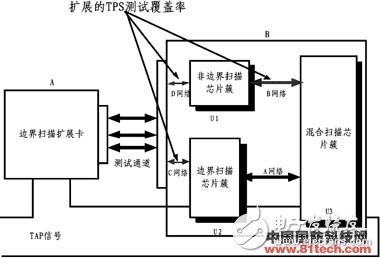
Figure 1 Schematic diagram of boundary scan MERGE test
Part B is the digital circuit BUT to be tested, and part A is a boundary scan expansion card independent of the BUT. The expansion card can be regarded as a digital circuit conforming to the IEEE 1149.1 boundary scan design specification. First, a complete digital circuit BUT is divided into the following parts: a non-boundary scan chip cluster (U1), a boundary scan chip cluster (U2), and a hybrid chip cluster (U3). The concept of "cluster" here means that multiple devices are collectively referred to as a "cluster". The range of clusters can be divided according to the specific circuit scale, which can be as small as a single IC or UUT (Unit Under Test), or as large as one. Complete BUT (Board Under Test).
(1) MERGE non-boundary scan chip cluster (U1): A non-boundary scan chip is an ordered subset of the entire BUT network and is a circuit with specific functions. In the MERGE concept, a separate functional model is established for the non-boundary scan chip clusters as an intermediate-level signal transmission model between the boundary scan chips, MERGE to the boundary scan link, combined with the EXTEST boundary scan command, through Capture IR- - "Shift IR--"Update IR--"Capture DR--"shift DR--" Update DR and other corresponding operations, to achieve the purpose of non-boundary scan cluster test through the boundary scan link.
(2) MERGE hybrid chip cluster (U3): The hybrid chip cluster refers to a hybrid circuit that contains both a non-boundary scan chip and a boundary scan chip (and may also contain some intermediate stage analog circuits). The idea of ​​MERGE is similar to (1). The verification of the model can be sampled by MO(Model Output) by applying a set of determined test vector sets APPLY to MI (Model Input) with a determined time delay. The test is implemented by comparing the response signal to the expected value stored in the register.
(3) MERGE BSEC (Boundary Scan External Card), BEDGE test of BUT in BUT edge circuit or BUT without boundary scan chip is implemented by BSEC. In the test, the BUT to be tested is used as a non-boundary scan cluster or a hybrid boundary scan cluster, and BSEC is regarded as a boundary scan chip cluster. The BUT, the interface circuit, and the boundary scan expansion card circuit are virtualized into a boundary scan chip by the MERGE method. The specific implementation of BUT is similar to (1) and (2).
Test system hardware designIn order to reduce the weight of the whole system and facilitate transportation and carrying, the front-end equipment of the test system uses the notebook computer as the main body to complete the realization of the system function and the interaction of the human-machine interface [3], and the GPIB-USB module and JTAG-Control. - PCI-USB controller that controls the programmable power supply (Agilent 6600) and BS Interface Pod modules. The core of the entire hardware design is BSEC (Boundary Scan Expansion Card), JTAG-Control-PCI-USB controller and BS Interface Pod module. The hardware block diagram of the system is shown in Figure 2.
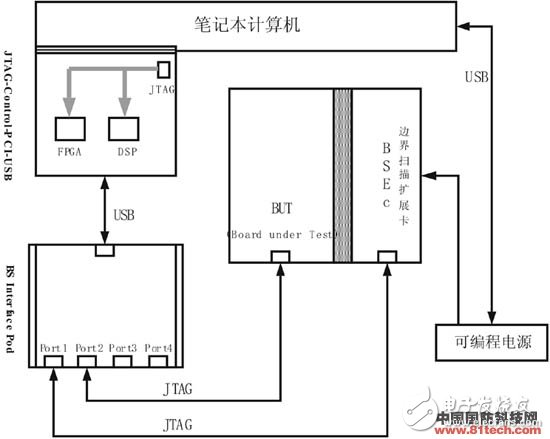
Figure 2 system hardware design block diagram
BSEC (Boundary Scan Expansion Card)Cixi Zhongyi Electronics Factory , https://www.cx-zhongyi.com