PID=port ID. In STP (SpTP), if the BID and path cost of the BPDU received on the port are the same, the PID is compared to select the blocked port. Digital TV multiplex system noun PID (Packet IdenTIfier) ​​In the digital TV multiplex system, its role is like the file name of a file, we can call it "flag code transmission package". Engineering Control and Mathematical Physics PID (Proportional Integral Derivative) English full name ProporTIon IntegraTIon DifferenTIation, which is a mathematical physics term. The PID consists of an 8-bit port priority plus a port number, the port number is low, and the default port number is 128.
PID regulation (PID regulation) A basic adjustment method of the control system in classical control theory. It is a linear regulation law with proportional, integral and differential action.
PID regulation (PID regulation) A basic adjustment method of the control system in classical control theory. It is a linear regulation law with proportional, integral and differential action. The role of PID adjustment is to deviate the given value r from the actual measured value y of the controlled variable. The proportional, integral and derivative signals of -r _y are combined into a control amount to control the controlled process. The expression of this control quantity is

Where K. For the proportional coefficient, T; is the integral coefficient, and 1'a is the differential coefficient. Increase the proportional coefficient K. It can reduce the static difference of the system, but when the KP is too large, the dynamic quality of the system will be deteriorated, causing the controlled amount to oscillate and even cause the closed-loop system to be unstable. The integral coefficient T; large indicates that the integral action is weak, otherwise the integral action is strong. Increasing T will slow down the process of eliminating static differences, but can reduce overshoot and improve stability. When the differential coefficient Ta increases, the differential action is strengthened, which helps to reduce overshoot, overcomes oscillation, stabilizes the system, speeds up the response of the system, and reduces the adjustment time, thereby improving the dynamic performance of the system. A wide range of analog or digital PID regulator products are available. Users only need to apply according to the actual application
Pid adjustment parameter setting method and setting techniquePID is the abbreviation of proportional, integral and differential. The difficulty of PID control is not programming, but the parameter setting of the controller. The key to parameter tuning is to correctly understand the physical meaning of each parameter. The principle of PID control can be understood by manual control of the furnace temperature. Reading this article does not require advanced mathematics.
1. Proportional control
The experienced operator manually controls the furnace temperature of the electric heating furnace to obtain very good control quality. There are many similarities between the PID control and the manual control strategy.
The following describes how the operator uses the idea of ​​proportional control to manually control the furnace temperature of the electric furnace. Assume that the furnace temperature is detected with a thermocouple and the temperature value is displayed with a digital meter. During the control process, the operator reads the furnace temperature with the eye and compares it with the furnace temperature set value to obtain the temperature error value. The potentiometer is then operated by hand to adjust the heating current to maintain the furnace temperature near a given value.
The operator knows the approximate position of the potentiometer when the furnace temperature is stable at a given value (we call it position L) and adjusts the corner of the potentiometer that controls the heating current based on the current temperature error value. When the furnace temperature is lower than the given value, the error is positive, and the rotation angle of the potentiometer is increased clockwise on the basis of the position L to increase the heating current. When the furnace temperature is greater than the given value, the error is negative. On the basis of the position L, the rotation angle of the potentiometer is counterclockwise, and the difference between the rotation angle and the position L is proportional to the error. The above control strategy is proportional control, that is, the proportional part of the PID controller output is proportional to the error.
There are various delays in the closed loop. For example, after adjusting the potentiometer corner, there is a large time delay until the temperature rises to the steady state value corresponding to the new corner. Due to the delay factor, the adjustment effect cannot be seen immediately after adjusting the potentiometer rotation angle. Therefore, the main reason for the difficulty in adjusting the closed-loop control system is the delay effect in the system.
If the proportional coefficient of the proportional control is too small, the difference between the adjusted potentiometer rotation angle and the position L is too small, and the adjustment force is not enough, so that the system output changes slowly, and the total time required for the adjustment is too long. If the proportional coefficient is too large, that is, the difference between the rotation angle of the potentiometer and the position L is too large, and the adjustment force is too strong, which will cause over-regulation, and even cause the temperature to fluctuate and fluctuate.
Increasing the proportionality factor makes the system responsive, speeds up regulation, and reduces steady-state errors. However, if the proportional coefficient is too large, the overshoot amount is increased, the number of oscillations is increased, the adjustment time is lengthened, the dynamic performance is deteriorated, and the proportional coefficient is too large to make the closed loop system unstable.
Simple proportional control is difficult to ensure that the adjustment is just right, completely eliminating the error.
2. Integral control
The integral in the PID controller corresponds to the area enclosed by the error curve and the coordinate axis in Fig. 1 (the gray portion in the figure). The PID control program is executed periodically, and the period of execution is called the sampling period. The computer program uses the sum of the rectangular areas in Figure 1 to approximate the exact integration. The TS in the figure is the sampling period.
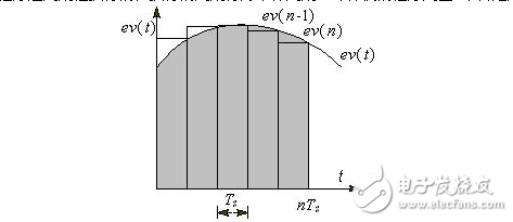
Figure 1 Schematic diagram of integral operation
Each time the PID operation is performed, a small portion proportional to the current error value ev(n) is added based on the original integrated value. When the error is negative, the increment of the integral is negative.
When the temperature is manually adjusted, the integral control is equivalent to periodically adjusting the angle of the potentiometer according to the error value at that time, and the incremental value of each adjustment is proportional to the error value at that time. When the temperature is lower than the set value, the error is positive, and the integral term is increased, so that the heating current is gradually increased, and the integral term is decreased. Therefore, as long as the error is not zero, the output of the controller will change continuously due to the integral action. The "large direction" of the integral adjustment is correct, and the integral term has the effect of reducing the error. Until the system is in a stable state, the error is always zero, the proportional part and the differential part are all zero, the integral part does not change, and it is just equal to the output value of the controller required at steady state, corresponding to the above temperature control. The position L of the potentiometer corner in the system. Therefore, the integral part is to eliminate the steady-state error and improve the control precision. The integral action is generally necessary.
The integral part of the PID controller output is proportional to the integral of the error. Because the integration time TI is in the denominator of the integral term, the smaller the TI, the faster the integral term changes, and the stronger the integral action.
3. PI control
The integral term in the controller output is proportional to the current error value and the accumulated value of past error values. Therefore, the integral action itself has severe hysteresis characteristics, which is detrimental to the stability of the system. If the coefficient of the integral term is set badly, its negative effect is difficult to correct quickly by the integral action itself. The proportional term has no delay, and as soon as the error occurs, the proportional portion will work immediately. Therefore, the integral action is rarely used alone. It is generally used in combination with proportional and differential to form a PI or PID controller.
PI and PID controllers overcome the shortcomings of simple proportional adjustment and steady-state error, and avoid the shortcomings of simple integral adjustment response and poor dynamic performance, so they are widely used.
If the controller has an integral action (for example, PI or PID control), the integral can eliminate the steady-state error of the step input, and the scale factor can be adjusted smaller.
If the integral action is too strong (that is, the integration time is too small), it is equivalent to the angle value of each trimmer potentiometer is too large, and its cumulative effect will make the dynamic performance of the system output worse, the overshoot amount will increase, and even the system will not stable. If the integral action is too weak (ie, the integration time is too large), the speed at which the steady-state error is eliminated is too slow, and the value of the integration time should be moderate.
4. Differential action
The differential of the error is the rate of change of the error. The faster the error changes, the larger the absolute value of the differential. When the error increases, its differential is positive; when the error decreases, its differential is negative. The differential portion of the controller output is proportional to the micro-integration of the error, reflecting the trend of the controlled amount.
If the experienced operator rises too fast, but has not reached the set value, according to the trend of temperature change, it is expected that the temperature will exceed the set value and overshoot will occur. Then adjust the rotation angle of the potentiometer and reduce the heating current in advance. This is equivalent to when the soldier shoots a distant moving target, taking into account the time of the bullet movement, it requires a certain amount of advance.
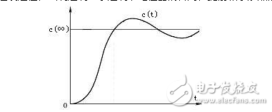
Figure 2 step response curve
c (∞) in Fig. 2 is the steady state value of the controlled quantity c (t) or the expected value of the controlled quantity, and the error e(t) = c (∞) - c (t). In the ascending phase of the startup process in Figure 2, at that time, the controlled amount has not exceeded its steady state value. However, because the error e(t) keeps decreasing, the differential of the error and the differential part of the controller output are negative, which reduces the output of the controller, which is equivalent to giving the braking effect in advance to hinder the controlled amount. Rise, so you can reduce the amount of overshoot. Therefore, the differential control has the characteristics of advance and prediction, and the control can be given in advance before the overshoot has occurred.
The fundamental reason for the oscillation and even instability of the closed-loop control system is that there is a large lag factor. Because the differential term predicts the tendency of the error to change, this "leading" effect can offset the effects of the lag factor. Appropriate differential control can reduce the overshoot and increase the stability of the system.
For controlled objects with large hysteresis characteristics, if the effect of PI control is not ideal, consider adding differential control to improve the dynamic characteristics of the system during the adjustment process. If the derivative time is set to 0, the differential part will not work.
The differential time is proportional to the strength of the differential action. The greater the differential time, the stronger the differential action. If the derivative time is too large, a “glitch†may appear on the response curve when the error changes rapidly.
The disadvantage of differential control is that it is sensitive to interference noise and reduces the ability of the system to suppress interference. To this end, the inertial filtering step can be added in the differential part.
5. The sampling period
The PID control program is executed periodically, and the period of execution is called the sampling period. The smaller the sampling period, the more the sampled value reflects the change of the analog quantity. However, too small will increase the computational workload of the CPU. The difference between the two adjacent samples will be almost unchanged, which will make the differential part of the PID controller output close to zero, so it is not appropriate to make the sampling period too small.
It should be ensured that when the controlled quantity changes rapidly (for example, during the rising phase of the startup process), there are enough sampling points, so that the important information in the acquired analog quantity is not lost because the number of sampling points is too small.
6. PID parameter adjustment method
When tuning the parameters of the PID controller, the parameters of the controller can be adjusted experimentally according to the qualitative relationship between the parameters of the controller and the dynamic performance and steady state performance of the system. Experienced debuggers can generally get more satisfactory debugging results faster. The most important issue in debugging is to know which parameter should be adjusted when the system performance is not satisfactory, and whether the parameter should be increased or decreased.
In order to reduce the parameters that need to be set, the PI controller can be used first. In order to ensure the safety of the system, relatively conservative parameters should be set at the beginning of debugging. For example, the proportional coefficient should not be too large, and the integration time should not be too small to avoid abnormal conditions such as system instability or excessive overshoot. Given a step reference signal, system performance information such as overshoot and regulation time can be obtained based on the output waveform of the controlled amount. The parameters of the PID should be adjusted repeatedly according to the relationship between the PID parameters and the system performance.
If the overshoot of the step response is too large, it may be stable or unstable after repeated oscillations. The proportional coefficient should be reduced and the integration time should be increased. If the step response does not have an overshoot, but the controlled amount rises too slowly and the transition time is too long, the parameters should be adjusted in the opposite direction.
If the speed of eliminating the error is slow, the integration time can be appropriately reduced to enhance the integral action.
Adjust the proportional coefficient and integration time repeatedly. If the overshoot is still large, you can add differential control. The differential time is gradually increased from 0, and the parameters of the proportional, integral and differential parts of the controller are repeatedly adjusted.
In short, the debugging of the PID parameters is a comprehensive process in which the parameters affect each other. Many attempts in the actual debugging process are very important and necessary.
7. Experimental verification
The experiment uses the PID control function block FB 41 of the S7-300 PLC. The controlled object consists of two series inertia links with time constants of 2s and 5s and a scale factor of 3.0. The trend graph of the display unit shows the response curve for a given curve and closed loop output.
The contents of this log are taken from the author's "PID parameter meaning and tuning method" published in the fifth issue of "Automation Application" magazine (see attachment). The experimental results given in this paper verify the parameters of the PID controller proposed in this paper. Setting method.
The author will release the STEP 7 project to learn the PID parameter tuning method using pure software simulation at the appropriate time.
Low Frequency Inverter,Off Grid Solar System Inverter,Sine Wave Inverter With Charger,Off Grid Pure Sine Inverter
GuangZhou HanFong New Energy Technology Co. , Ltd. , https://www.gzinverter.com