What is topology? The so-called circuit topology is the way in which the power device and the electromagnetic component are connected in the circuit, and the design of the magnetic component, the design of the closed-loop compensation circuit and all other circuit component designs depend on the topology. The most basic topologies are Buck (buck), Boost (boost) and Buck/Boost (buck/boost), single-ended flyback (isolation flyback), forward, push-pull, half-bridge and full-bridge Variant.
The following briefly introduces the common switching power supply topology.
Buck circuitThe first thing we want to talk about is the Buck circuit.
The Buck circuit also becomes a step-down converter. Its circuit diagram is as follows:
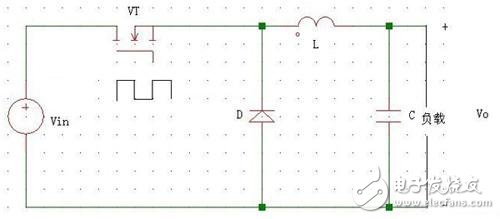
Transistors, diodes, inductors, capacitors, and loads form the main loop. The lower control loop typically uses a PWM (Pulse Width Modulation) chip to control the duty cycle to determine the on and off of the transistor.
The function of the Buck circuit is to convert the DC voltage Ui into a DC voltage Uo for the purpose of voltage reduction.
Flyback converterThe flyback switching power supply refers to a switching power supply that uses a flyback high-frequency transformer to isolate the input and output circuits, and has a forward switching power supply corresponding thereto.
Flyback (FLY BACK), specifically when the switch is turned on, the output transformer acts as an inductor, and the electrical energy is converted into magnetic energy. At this time, the output loop has no current;
Conversely, when the switch is turned off, the output transformer releases energy, the magnetic energy is converted into electrical energy, and there is current in the output.
In the flyback switching power supply, the output transformer also acts as a storage inductor, and the entire power supply is small in size and simple in structure, so it is widely used. The most widely used is a single-ended flyback switching power supply.
Advantages: less components, simple circuit, low cost, small size, and can output multiple isolated voltages at the same time;
Disadvantages: The switch tube is subjected to high voltage and the output transformer utilization is low, which is not suitable for high-power power supply.
Boost circuit
The Boost circuit is the most basic flyback converter. The Boost converter is also called a boost converter, a parallel switch circuit, and a three-terminal switching type boost regulator.
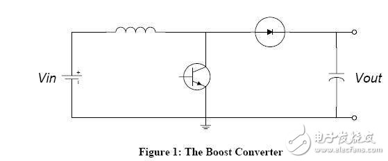
The above picture is the Boost circuit diagram. The Boost circuit is a boost circuit whose output voltage is higher than the input voltage.
Buck/Boost converter
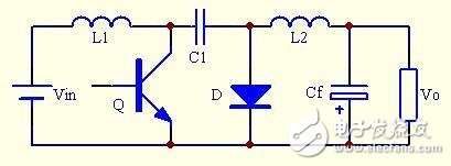
Buck/Boost converter: also known as buck-boost converter, is a single-tube non-isolated DC converter whose output voltage can be lower or higher than the input voltage, but its output voltage polarity and input voltage in contrast. The Buck/Boost converter can be thought of as a series connection of a Buck converter and a Boost converter, which combines the switching tubes. Its circuit diagram is as follows:
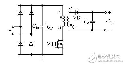
The Buck and Boost circuits mentioned above are both output and input, and there is no isolation on the circuit. After the transformer is used, the output is electrically isolated from the input and can be output in multiple ways. The flyback converter is the simplest of the isolated converters. It is divided into two working modes, a discontinuous mode flyback converter and a continuous mode flyback converter. Isolation of the flyback transformer circuit diagram below!
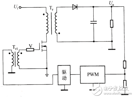
Here, the isolation transformer functions as a transformer and a storage inductor.
Forward converterWhen the transistor is turned on, energy is transferred to the load, and the converter maintained by the output stage LC circuit when turned off becomes a forward converter. It has multiple modes such as single-ended forward and double-ended forward converters.
Single-ended forward converter
First look at the schematic:
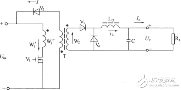
Single-ended forward transformers are also known as "buck" converters. It is named because it transfers energy to the output while the primary winding is connected to the power supply Vi.
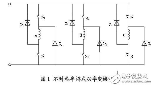
Double-ended forward converter
Double-ended forward is also called asymmetric bridge. It consists of two power tubes and two diodes. But only the power tube can be controlled to conduct, the transformer is unidirectionally magnetized, and there is no bridge arm straight-through problem. Strong interference ability.
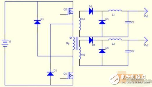
The characteristic of this circuit structure is: symmetrical structure, the primary side of the pulse transformer is two symmetrical coils, the two switch tubes are connected in a symmetrical relationship, and the wheel is broken, and the working process is similar to the class B push-pull power amplifier in the linear amplifying circuit.
When S1 and S2 are turned on in turn, the primary side will generate an alternating current through the power supply-S1-T-C2-power supply and the power supply-C1-T-S2-power supply, thereby generating alternating ripple current on the secondary side. The full-wave rectification is converted into a DC signal, which is then filtered by L and C and sent to the load. Again, this circuit is equivalent to a buck topology.
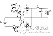
The full-bridge power converter is suitable for high-power, high-voltage applications. Its circuit diagram is as follows:
Buck circuit
The Buck circuit is a buck converter, which is mainly used in the field of low voltage and high current, in order to solve the conduction loss problem of the freewheeling tube.
The general diode freewheeling has a large on-resistance, and the loss is large when applied to a large current.
In addition, replacing the diode with a MOS transistor with a very small on-resistance can solve the loss problem, but at the same time put forward higher requirements for the drive circuit.
After applying the synchronous rectification technology to the Buck circuit and replacing the diode with the MOS tube, the circuit topologically integrates the Buck and Boost converters, which provides a possibility for bidirectional DC/DC conversion.
In the case where one-way lifting and lowering pressure is required and the energy can flow in both directions, it has great application value. For example, when applied to a hybrid electric vehicle, it is supplemented by a three-phase controllable full-bridge circuit, which can realize charging and discharging of the battery.
Flyback converter
(1) Boost circuit
In practical applications, the design of the booster circuit is often involved. For a large power output, such as a DC/DC boost circuit of 70 W or more, it is difficult to achieve high power boost due to the limitation of the internal switching transistor of the dedicated boost chip. The conversion, and the price of the chip is expensive, and is greatly limited in practical applications.
Considering that the Boost boost structure has a large choice of external switch tubes, a DC/DC boost circuit with high power output can be designed by selecting a suitable control chip.
(2) Buck/Boost converter
The basic non-isolated and isolated Buck/Boost converters are widely used in small and medium power DC/DC converters due to their simple circuit topology, high input voltage range, buck-boost, and high reliability during load short-circuit.
Forward converter
The double-ended forward converter overcomes the shortcomings of high switching voltage stress in the forward converter. Each switching tube only needs to withstand the input DC voltage, and the magnetic reset of the transformer can be ensured without using a special magnetic reset circuit.
Each of its bridge arms is composed of a diode and a switch tube in series. There is no danger of straight-through of the bridge arm and high reliability.
Therefore, the double-ended forward converter has the advantages that other converters cannot match, and it has become one of the most widely used topologies in the medium and large power converters.
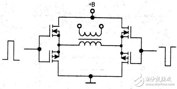
Push-pull converter
The push-pull converter is the earliest application topology in the converter, and is still widely used in DC/DC converters and DC/AC inverters. Its output can be higher or lower than the input DC voltage.
The closed-loop main output maintains output stability when the grid and load change, and the output can be well adjusted for grid changes.
Half bridge power circuit
The primary winding voltage of the half-bridge converter is only the input voltage. If the primary output current is twice as large as the push-pull, the power supply with a larger current rating is required.
The half-bridge converter is suitable for applications with high input voltage and medium output power, since the voltage rating on the power tube is ideally the input DC voltage.
Full bridge power circuit
Full-bridge power converters are suitable for high-power, high-voltage applications. It has been pointed out above that the power transistor operating in the half-bridge power conversion circuit is subjected to a maximum voltage 1/2 less than that of the transistor operating in the push-pull conversion circuit. However, if the output power requirements are the same, the operating current of the transistor will increase. Big.
The full-bridge power conversion circuit is a high-power conversion circuit that can maintain the low voltage of the half-bridge circuit power switching device and the small current carrying current of the push-pull circuit.
The main rod of the log-periodic antenna is two parallel thin-walled square metal tubes, which are fixedly connected by splint and installed on the bracket through horseshoe bolts. The bracket is fixed on the strut, and the steel Cable is connected to the sliding sleeve on the strut. The strut is inserted into the user support rod. The antenna vibrators are paired in pairs and fastened on the outside of the two main rods by the clamping frame. The high-frequency coaxial cable passes through the main rod. There is a sealing plug at the joint to seal and inner, and the outer conductor Connector connects the cable shielding wire and core wire with the main rod wall. The antenna can be adjusted freely in three-dimensional space. Compared with similar antennas, the length is shortened by nearly half. It is easy to set up, install, adjust, transport and low cost.

Log Periodic Antenna,LPDA Antenna ,Periodic antenna,Periodic Log Antenna,Periodic antenna hf
Yetnorson Antenna Co., Ltd. , https://www.xhlantenna.com