1 Introduction
With the development of science and technology, ARM has become more and more widely used in all aspects of society. ARM chips are widely used in wireless products, PDAs, GPS, networking, consumer electronics, STB and smart cards. The S3C4510B is an ARM7TDMI-based RISC microprocessor manufactured by SAMSUNG, with a frequency of up to 50 MHz. The liquid crystal display is a human-computer interaction interface that reflects the input/output of the system in the embedded system. The liquid crystal display is widely used due to its many advantages such as micro power consumption, small size, rich display content, modularity, and simple interface circuit. Since the S3C4510B is mainly designed for Ethernet application systems, there is no LCD control module inside, which causes inconvenience in some human-computer interaction. We use the S3C4510B's general-purpose I/O port to control the software and hardware methods of the LCD display, and achieve the same functions as the LCD control module.
2 Introduction to S3C4510B
The S3C4510B is a cost-effective 16/32-bit (reduced instruction set) RISC microcontroller based on Ethernet application system. It contains an ARM7TDMI RISC processor core designed by ARM. The ARM7TDMI is low power and high. Performance of the 16/32 core. Support large and small end mode, internal architecture is big endian mode, external memory can be big and small end mode; JTAG based debugging scheme; boundary scan interface. Supports ROM/SRAM, FLASH, DRAM and external I/O operation in 8/16/32 bit mode. Ideal for applications that are sensitive to price and power consumption.
In addition to the ARM7TDMI core, the S3C4510B's more important on-chip peripheral functional modules include:
u 2 HDLC channels with buffer descriptors (Buffer DescripTIor);
u 2 UART channels;
u 2 GDMA channels;
u 2 32-bit timers;
u 18 programmable I/O ports.
The S3C4510B provides 18 programmable general purpose I/O ports that each user can configure as an input mode, an output mode, or a special function mode, controlled by the on-chip Special Function Registers IOPMOD and IOPCON. The transferred data is stored in the register IOPDATA.
The operating modes of Port 0 to Port 7 are controlled only by the IOPMOD register. In addition, by setting the IOPCON register, Port 8 to Port 11 can be used as inputs for external interrupt requests INTREQ0 to INTREQ3. Port 12 and port 13 can be used as inputs to the external DMA requests XDREQ0, XDREQ1. Port 14 and port 15 can be used as the response signals XDACK0 and XDACK1 of the external DMA request, port 16 can be used as overflow 0 of timer 0, and port 17 can be used as overflow 1 of timer 1.
The lower 18 bits of the I/O port mode register IOPMOD are used to configure the operation of I/O ports P17 to P0. 0 is the input and 1 is the output.
3 OCMJ4X8C LCD Module
This LCD adopts ST7920 Chinese graphics control chip produced by Taiwan Yuchuang Electronics Co., Ltd. The LCD screen is 128X64 points. It can display letters, numbers, Chinese characters and graphics, and has a mixed display function of drawing and text. Built-in 2M Chinese character ROM (CGROM) provides a total of 8192 Chinese characters (16X16 dot matrix), 16K half-width font ROM (HCGROM) provides a total of 126 symbol fonts (16X8 dot matrix), 64X16-bit font generation RAM (CGRAM), in addition, the drawing display screen provides a 64X256 dot drawing area (GDRAM), which can be mixed with the text screen. Provide multi-function instructions: Display clear, Return home, Display on/off, Cursor on/off, Display character blink , Cursor shift, Display shift, VerTIcal line scroll, By_line_reverse display, Standby mode.
OCMJ4X8C (128X64) pin description (Table 1)
Pin number pin symbol description
1VSS logic power ground
2VDD logic power +5V
3NC no connection
4RS (CS) High: Data / Low: Instruction (serial input chip select)
5R/W (SID) high: read/low: write (serial data)
6E (SCLK) enable (serial clock)
7-14DB0-DB7 parallel data terminal
15PSB high: parallel/low: serial
16NC no connection
17/RST system reset low active
18NC no connection
19LEDA backlight power +5V
20LEDK backlight power supply 0V
Hardware circuit:
For this LCD module, when the PSB is tied high, the module will enter parallel mode, and the parallel mode is divided into 8-bit and 4-bit transmission modes. When the PSB segment is tied low, the module will enter serial mode. The design uses a 4-wire serial input, so ground the PSB. And the backlight power terminal LEDA is connected to the power supply +5V, LEDK is grounded.
Then, the IO port of the S3C4510B is connected to the liquid crystal module as follows: IO3 - SCLK, IO5 - CS, IO7 - SID, IO9 - / RST. It should be noted here that the corresponding special function registers of S3C4510B need to be set by software to set IO3, IO5, IO7, IO9 to output mode. The hardware connection diagram is shown in Figure 1:
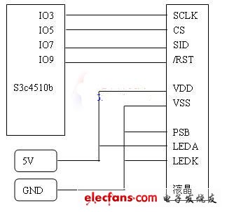
Figure 1: Hardware connection diagram
ZGAR Glo-X Prefilled Cartridge
Zgar International (M) SDN BHD , https://www.zgarecigarette.com