The ARM processor has a total of 37 registers and is divided into several groups (BANK). These registers include:
â— 31 general-purpose registers, including the program counter (PC pointer), are 32-bit registers.
â— 6 status registers, which are used to identify the working status of the CPU and the running status of the program, all of which are 32-bit. Currently only a part of them are used.
The ARM microprocessor supports seven operating modes, namely:
â— usr (user mode): ARM processor normal program execution mode.
â— fiq (fast interrupt mode): for high-speed data transmission or channel processing
â— irq (external interrupt mode): for general interrupt processing
â— svc (management mode): the protection mode used by the operating system
â— abt (data access termination mode): This mode is entered when data or instruction prefetch is terminated and can be used for virtual storage and storage protection.
â— sys (system mode): Runs a privileged operating system task.
â— und (undefined instruction abort mode): This mode is entered when an undefined instruction is executed and can be used to support software emulation of the hardware coprocessor.
The operating mode of the ARM microprocessor can be changed by software or by external interrupt or exception handling.
Most applications run in user mode, and some protected system resources are not accessible when the processor is running in user mode.
In addition to the user mode, all the other six modes are called non-user mode, or privileged mode (Privileged Modes); in addition to the user mode and system mode, five kinds of exception modes (Exception Modes) are often used for processing. Interrupts or exceptions, as well as the need to access protected system resources.
The ARM processor has a corresponding set of registers corresponding to each processor mode. That is, in any of the processor modes, the accessible registers include 15 general-purpose registers (R0 to R14), one to two status registers, and a program counter. Among all the registers, some are the same physical register shared in 7 processor modes, while others have different physical registers in different processor modes.
The ARM processor has two working states of 32-bit ARM and 16-bit Thumb. A word-aligned ARM instruction is executed in a 32-bit ARM state, and a half-word aligned Thumb instruction is executed in a 16-bit Thumb state.
In the Thumb state, the program counter PC (Program Counter) uses bit [1] to select another halfword.
The ARM processor can switch between the two operating states, and the switching does not affect the mode of the processor or the contents of the registers.
(1) When the status bit (bit [0]) of the operand register is 1, the BX instruction is executed to enter the Thumb state. If the processor enters an exception in the Thumb state, it automatically transitions to the Thumb state when exception handling (IRQ, FIQ, Undef, Abort, and SWI) returns.
(2) When the status bit (bit[0]) of the operand register is 0, the BX instruction is executed to enter the ARM state, and the processor performs exception processing (IRQ, FIQ, Reset, Undef, Abort, and SWI). In this case, put the PC in the exception mode link register. It is also possible to enter the ARM state by executing from the exception vector address.
n ARM processor register organizationThe ARM processor's 37 registers are arranged in partially overlapping groups and cannot be used in any mode. The use of registers is related to processor state and operating mode. As shown in Figure 2.3.1, each processor mode uses a different register bank. Among them, 15 general-purpose registers (R0 to R14), 1 or 2 status registers, and program counters are common.
General purpose register
The general-purpose registers (R0 to R15) can be classified into three types: non-packet registers R0 to R7, group registers R8 to R14, and program counter R15.
(1) Do not group registers R0 to R7
The non-packet registers R0 to R7 are true general-purpose registers that can operate in all processor modes without implied special use.
(2) Group register R8 ~ R14
The packet registers R8-R14 depend on the current processor mode, and each mode has a dedicated packet register for fast exception handling.
Registers R8 to Rl2 can be divided into two sets of physical registers. One group is used for FIQ mode and the other group is used for modes other than FIQ. Group 1 accesses R8_fiq~R12_fiq, allowing fast interrupt processing. The second group accesses R8_usr to R12_usr, and registers R8 to R12 do not have any specified special purpose.
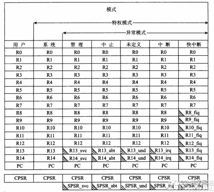
Indicates that the general register used by the user or system mode has been replaced by another register specific to the exception mode.
The registers R13 to R14 can be divided into physical registers of six groups. One is used for user mode and system mode, while the other five are used for five exception modes: svc, abt, und, irq, and fiq. You need to specify their mode when accessing, such as: R13_, R14_; where: You can choose one of the six modes: usr, svc, abt, und, irq, and fiq.
Register R13 is typically used as a stack pointer, called SP. Each exception mode has its own group R13. Usually R13 should be initialized to point to the stack allocated by the exception mode. At the entry, the exception handler saves the values ​​of the other registers used to the stack; when it returns, it reloads the values ​​into the registers. This exception handling method guarantees that the state of the execution program will not be unreliable after the exception occurs.
Register R14 is used as a subroutine link register, also known as the Link Register LK (Link Register). A backup of R15 is obtained when the link branch (BL) instruction is executed. In other cases, R14 is treated as a general purpose register. Similarly, when an interrupt or exception occurs, or when an interrupt or exception program executes a BL instruction, the corresponding packet registers R14_svc, R14_irq, R14_fiq, R14_abt, and R14_und are used to hold the return value of R15.
The FIQ mode has seven grouped registers R8 to R14, which are mapped to R8_fiq to R14_fiq. In the ARM state, many FIQ processes do not have to save any registers. The User, IRQ, Supervisor, Abort, and Undefined modes each contain a mapping of two grouped registers, R13 and R14, allowing each mode to have its own stack and link registers.
(3) Program counter R15
Register R15 is used as a program counter (PC). In the ARM state, bits [1:0] are 0, and bits [31:2] hold the PC. In the Thumb state, Bit [0] is 0, and Bit [31:1] holds the PC. Although R15 can also be used as a general-purpose register, it is generally not used because there are some special restrictions on the use of R15. When these restrictions are violated, the execution result of the program is unknown.
1 Read the program counter. The value of R15 read by the instruction is the instruction address plus 8 bytes. Since the ARM instruction is always word-aligned, the bits [1:0] of the read result value are always 0 (in the Thumb state, the situation has changed). The read PC is primarily used to quickly position-independently approach adjacent instructions and data, including position-independent transfers in the program.
2 Write the program counter. The usual result of writing R15 is to use the value written to R15 as the instruction address and transfer at this address. Since ARM instructions require word alignment, it is often desirable to write bits [1:0] = 0b00 to the value of R15.
Since the ARM architecture uses multi-stage pipeline technology, for the ARM instruction set, the PC always points to the address of the next two instructions of the current instruction, that is, the value of the PC is the address value of the current instruction plus 8 bytes.
Program status registerRegister R16 is used as the Program Status Register CPSR (Current Program Status Register). The CPSR can be accessed in all processor modes. The CPSR contains condition code flags, interrupt disable bits, current processor mode, and other status and control information. Each exception mode has a Program Status Save Register SPSR (Saved Program Status Register). When an exception occurs, the SPSR is used to reserve the state of the CPSR.
The format of CPSR and SPSR is as follows:
(1) Condition code mark
N, Z, C, V (Negative, Zero, Carry, oVerflow) are Condition Code Flags, their contents can be changed by the result of arithmetic or logic operations, and can determine whether an instruction is carried out. The condition code flag in the CPSR can be detected by most instructions to determine if the instruction is executed. In the ARM state, most instructions are conditionally executed. In the Thumb state, only branch instructions are conditionally executed. Usually the condition code flag is modified by executing a compare instruction (CMN, CMP, TEQ, TST), some arithmetic operations, logic operations, and transfer instructions.
The usual meaning of the condition code mark is as follows:
N: If the result is a signed twos complement, then N = 1 if the result is negative; N = 0 if the result is positive or 0.
Z: If the result of the instruction is 0, it is set to 1 (usually the result of the comparison is "equal"), otherwise it is set to 0.
C: Can be set by one of the following four methods:
One-addition (including comparison instruction CMN). If the addition produces a carry (ie, an unsigned overflow), C is set to 1; otherwise, it is set to 0.
One-subtraction (including comparison instruction CMP). If the subtraction produces a borrow (ie, an unsigned overflow), then C is set to 0; otherwise, it is set.
One - For the non-addition/subtraction instruction combined with the shift operation, C is set to the last 1 bit of the shifted value.
One - For other non-addition/subtraction instructions, C usually does not change.
V: It can be set in the following two ways, namely
One - For an addition or subtraction instruction, when a signed overflow occurs, V is set to 1, and the operand and result are considered to be signed integers in the complement form.
One - For non-addition/subtraction instructions, V usually does not change.
(3) Control bit
The lowest 8 bits of the Program Status Register PSR (Program Status Register), I, F, T, and M[4:0] are used as control bits. Change the control bit when an exception occurs. The processor can also be changed by software when in privileged mode.
a. Interrupt disable bit
I: set to 1, the IRQ interrupt is disabled;
F: Set to 1 to disable the FIQ interrupt.
bT position
T=0 indicates ARM execution;
T=1 indicates that Thumb is executing.
c. Mode control bit
M4, M3, M2, Ml, and M0 (M[4:0]) are mode bits that determine the operating mode of the processor, as listed in the table.
M[4:0] working mode accessible registers
10000 user mode PC, CPSR, R14 to R0
10001FIQ mode PC, R7~R0, CPSR, SPSR_fiq, R14_fiq~R8_fiq
10010IRQ mode PC, R12~R0, CPSR, SPSR_irq, R14_irq, R13_irq
10011 management mode PC, R12~R0, CPSR, SPSR_svc, R14_svc, R13_svc
10111 abort mode PC, R12~R0, CPSR, SPSR_abt, R14_abt, R13_abt
11011 Undefined mode PC, R12~R0, CPSR, SPSR_und, R14_und, R13_und
11111 system mode PC, R14 ~ R0, CPSR (ARM v4 and above)
Not all combinations of mode bits define an efficient processor mode. The results of other combinations are unpredictable.
(4) Other bits
The other bits of the program status register are reserved for future expansion.
Dash Mining Machine:Bitmain Antminer D7 (1286Gh),Baikal BK-G28,Baikal BK-X,Baikal Giant+ A2000,Innosilicon A5 DashMaster,iBeLink DM22G,Bitmain Antminer D3 (15Gh),StrongU STU-U6,Bitmain Antminer D5 (119Gh)
In short, Dashcoin Dash is a variant of the Bitcoin cryptocurrency that runs on the same blockchain network. Dashi, which combines the words "digital" and "cash," has become one of the most widely watched counterfeit coins in recent months. Originally released as "XCoin", it was later changed to "Darkcoin" and later Dash.
Arguably the biggest benefit of Dashi is that its transactions can be sent completely anonymously, just like legal cash payments. This is achieved by using a hybrid protocol that operates a dedicated network of servers called Masternodes. While Bitcoin operates only a single-layer network of miners, Dashcoin uses these master nodes as additional layers to its network, eliminating the need for a trusted third party to authorise a transaction that could compromise the anonymity of any payment.
Another major difference between Dashcoin and Bitcoin is that the former distributes mining rewards between its mining community, participants holding a specified amount of Dash, and the Dash community's long-term development fund.
Dash Miner,Dash Mining Machine,Bitmain antminer d7, D7 miner,X11 algorithm
Shenzhen YLHM Technology Co., Ltd. , https://www.asicminer-ylhm.com