Machine vision and robotics systems can be integrated into one application using LabVIEW and the ImagingLab RoboTIcs library for DENSO. This article describes how to calibrate between a machine vision system and a robotic system using the same coordinate system.
BackgroundThis article is part of the "ImagingLab RoboTIcs Library Reference Guide for DENSO" and assumes that you are already familiar with the basic usage of the library. If you need to review these topics or read the introduction to the robot library, please click on the link to the reference guide above.
The bridge between the machine vision system and the robot is a shared coordinate system. The machine vision system locates the corresponding part and reports the position to the robot, but to instruct the robot to move to that position, the system must convert the coordinates to a unit acceptable to the robot. Calibration allows the machine vision system to report position in real world units (for example, millimeters), which is the unit used by the robot's Cartesian coordinate system. A common method of calibration is to use a point grid. For further information on image calibration, see the NI Vision Concepts Handbook. You can calibrate your machine vision system with a point grid and calibrate your robot with a machine vision system. When calibrating a machine vision system, you must select the origin to define the xy plane. Usually select the point at the corner as the origin and then select the row or column as the x-axis.
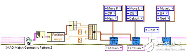
The method of creating a coordinate system for a robot is similar, so you use the origin of the calibration network of the machine vision system as the origin of the robot. The method is simple, as long as the robot is moved to this point, the position is stored as a position variable on the robot controller, the robot is moved in the x-axis and the y-axis, and these positions are stored as position variables. You can store these position variables using LabVIEW or DENSO's teaching mode. Once this is done, you can use DENSO's teaching mode to automatically calculate the coordinate system or work area based on the three previously stored position variables. To use the automatic calculation tool of DENSO's teaching mode, select Arm >> Extras >> Work >> Auto Calculate from the main screen. In the open automatic calculation menu, you only need to select the position variable corresponding to the origin, x-axis and xy plane stored previously. After the automatic calculation is complete and the recently created work is set to the currently used job, you can directly enter the calibrated machine vision system position directly into the robot's Cartesian Motion VI. See Figure 10 for a simple example of passing these coordinates. These parameters that are directly input to the Robot Movement VI also include the matching angle, which is the output of the geometric pattern matching result of the machine vision system. Other calibration methods can also directly input coordinate system parameters instead of using the automatic calculation function built into the teaching mode. You can do this with DENSO teaching mode or LabVIEW. See the DENSO manual for more information on robot calibration methods.
In most cases, the camera is in a fixed position relative to the robot, which means that after you have finished calibrating the robot and machine vision system, you can use the machine vision code to directly enter the calibration position output into the Robot Motion VI. Here we use absolute movement. In other cases, you can attach the camera to a tool at the end of the robot or to another mobile device. Because the camera's viewing angle will constantly change, you must either update the calibration based on the angle of view or use relative motion. If relative motion is used, the target position is given as an offset from the current position, for example the camera requires the target to be centered in the frame of each acquisition. If the target is off center, the image gives the command to move the robot a corresponding distance until the target is in the center. You can also use a hybrid system if the fixed camera provides absolute motion near the part or moves to the collection area. Use the second camera to get precise guidance on reaching the target position.
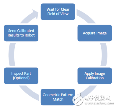
4. Parallel processingThe ImagingLab RoboTIcs library for DENSO contains sequential execution APIs that can be executed in the order in which they are written, but in many applications, robot control code is not necessarily the only code that needs to be executed. Machine vision acquisition and processing, HMI and human machine interfaces, alarm management, supply device control, and other communication programs are all tasks that need to be run in parallel with the robot control program. LabVIEW has many architectures that can manage multiple tasks, such as master-slave architecture or producer-consumer architecture, and you can choose an architecture for your specific application. In the application of vision-oriented robots, image acquisition and processing does not need to be executed sequentially with the robot instructions, so we can use parallel processing architecture to let these functions run at the same time, because the robot does not need to wait for the machine vision code to run before moving. So the movement of the robot can be more continuous and smooth. After the robot moves out of the viewable area, you can capture new images and perform corresponding geometric pattern matching and detection while the previous parts are assembled or moved to the target position. Therefore, when the previous part is placed, the new part is ready to be sent to the Robot Motion VI. The following figure is an example of a flow chart that implements machine vision code running in parallel with the robot VI.
Laptop power adapter charger for Macbook, Macbook Air and Macbook Pro.
45w, 60w, 80w charger with Magsafe 1 or Magsafe 2 connector.
Four replacement ac plugs for your choices, US / EU / UK / AU plug as your requirement.
Stable output and high charging efficiency.
Elegant outlook design as original one, touch smoothly and comfortable.
Easy carry if you want to take your computer outside for business or travel.
Original charger is good, but as a replacement, our product has more reasonable price when your original charger is broken.
And, the market of the replacement adapters becomes bigger and bigger. People would rather buy a copy one then the original because of the price.
But at the same time, people worry about that they will buy something defective. So the problem comes, how to buy a good quality one with a good price?
As a professional power adapter manufacturer, we have excellent R&D team, skilled staffs and responsible after-sale service. All your benefits can be under protected after you buy products for our company.
Our certificates :ISO9001:2008 & ISO14001:2004 , CCC , CE , FCC , ROHS.
All our products has 1 year warranty. In other words, if you get the dad products which are not damaged physically from us in one year, we will replace you the new one or the whole bulk order.
Macbook Adapter,45W Adapter For Macbook,45W Charger For Macbook,60W Charger For Macbook,Macbook Charger
Shenzhen Waweis Technology Co., Ltd. , https://www.waweis.com