For the AC position servo control system, the PC-based development platform is used to control with the conventional pid regulator. As long as the parameters are properly set, the mechanical accuracy of the system (motion axis, gear, motor screw drive) is controlled. Electrical control accuracy (encoder pulse) can be improved within a certain error range
System composition principle
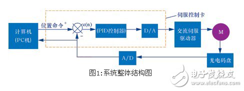
The system consists of four parts, namely microcomputer, servo control card, AC servo speed control system and sensing detection. The main control microcomputer is connected to the control card, and can send the position or speed command through the data line, set the pid adjustment parameter, and perform digital-to-analog (d/a) conversion. The analog signal is amplified by the AC servo amplifier to drive the servo motor. The motor shaft end is equipped with an incremental photoelectric code disc, and the feedback signal (a, b, in pulse) is provided through the photoelectric code disc to complete the position feedback of the position servo system to form a semi-closed loop system. Generally, the photoelectric code disc is mounted on the shaft end of the non-loaded shaft of the motor, which is convenient for installation and avoids the vibration and deformation of mechanical parts adversely affecting the position control system. The sensing element in the position feedback loop—incremental photoelectric encoder transmits the real-time displacement (or corner) variation of the moving member to the field control station (PC) for long-term transmission in the form of a and b phase differential pulses for encoder pulse counting. To obtain the digitized position information, after the main control microcomputer calculates the deviation between the given position and the actual position (ie, the feedback position), the corresponding pid control strategy is adopted according to the deviation range, and the digital control function is converted into a simulation through digital-to-analog conversion. The voltage is controlled and output to the servo amplifier, which finally adjusts the motor motion to achieve the desired value.

Servo control method
The commonly used method in industrial control is the pid regulator. Although with the development of modern AC speed regulation technology, various new control algorithms have emerged, such as adaptive control, expert system, intelligent control and so on. From the theoretical analysis, many control strategies can achieve good motor dynamic and static characteristics, but due to the complexity of the algorithm itself, and the simulation of the system is more troublesome, it is difficult to implement in the actual system, for the traditional pid regulator In terms of its advantages, the algorithm has simple algorithm, easy parameter setting, strong robustness, strong adaptability and high reliability. These features make pid controller widely used in industrial control field. It is not complicated for the control object in the CNC system, and it is easier to achieve the desired effect with the pid regulator.
Position loop pid control algorithm
In the digital pid adjustment control system, the purpose of introducing the integral link is to eliminate the static difference and improve the accuracy. However, when the process starts or ends or the set value is greatly increased, the integral accumulation occurs, causing a large overshoot of the system. Even oscillating, this is disadvantageous for the operation of the servo motor. In order to reduce the influence of the integral correction on the dynamic performance of the control system during the operation of the motor, the integral separation pid control is justified. When the error between the real position and the desired position of the motor is less than a certain position, the integral correction link is restored. Eliminate the steady state error of the system.
The integral separation pid control algorithm needs to set the integral separation valve ε. When |e(k)| ε, that is, when the deviation value is large, pd control is used to ensure the servo motor position control accuracy.
The discretization pid control formula is:

Where k is the sample number, k=0, 1, 2...;
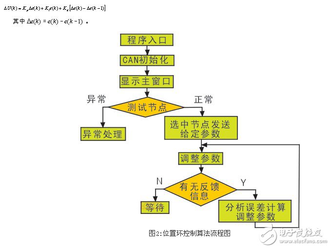
Kp, ki, and kd represent the ratio, integral, and differential coefficient, respectively. In practice, if the actuator needs the increment of the control amount, the incremental pid control formula can be obtained according to the stacking principle:

Control system parameter setting
The main control microcomputer sends the pid parameter to the control card to see if the given parameters meet the requirements of the control system. The process needs to be implemented by parameter tuning. The main task of parameter tuning is to determine kp, ki, kd and sampling period t, and the proportional coefficient kp is increased, so that the action of the servo drive system is sensitive, the response is accelerated, and the overshoot causes oscillation, the adjustment time is lengthened; the integral coefficient ki increases. Can eliminate the system steady-state error, but the stability is reduced; differential control can improve the dynamic characteristics, the overshoot is reduced, and the adjustment time is shortened. The usual methods are the extended critical scale method and the extended response curve method, and the normalized parameter tuning method. These methods are derived from the use of Ziegler-Nichols (ziegler-nichols rule), which can usually be considered as a model with a delay phase in the AC servo system (a first-order link with hysteresis):

The one-stage response characteristic parameters k, l, and t in the equation can be extracted from the s-type response curve shown in FIG. It is not difficult to obtain these parameters for the actual system. The step input excitation can be applied to the system to obtain the response curve, and then the characteristic parameters are obtained according to the curve. It can then be obtained by the ziegler-nichols tuning rule:

The choice of sampling period in a digital system is closely related to the stability of the system. On the one hand, it is necessary to satisfy Shannon's theorem, that is, ωs≥2ωmax The actual system input and feedback maximum frequency ωmax is difficult to measure. On the other hand, the sampling period does not have an accurate calculation formula, which can only be selected according to empirical rules according to engineering applications. For motor control systems , requires a shorter time sampling period, usually tens of milliseconds.
For the AC position servo control system, the PC-based development platform is used to control with the conventional pid regulator. As long as the parameters are properly set, the mechanical accuracy of the system (motion axis, gear, motor screw drive) is controlled. Within a certain error range, the electrical control accuracy (encoder pulse) can be improved, the robustness is strong, and the position of higher precision position control can be achieved in many occasions.
| Puffs | 3500 |
| E-liquid | 2-10 ML |
| Nic Content | CBD,2%,5% |
3500 Plus Puffs CBD Disposable ecig have a completely enclosed design, reducing the need for charging and replacing cartridges. The no-charge design also reduces the occurrence of faults. It is understood that with rechargeable e-cigarettes, each cartridge needs to be charged at least once and the battery efficiency is extremely low, while the design of disposable ecig can solve this problem very well.
3500 Plus Puff E-Cigarette,3500 Plus Puff E-Cigarette For Sale,Best 3500 Plus Puff E-Cigarette,Best 3500 Plus Puff E-Cigarette For Sale
Shenzhen E-wisdom Network Technology Co., Ltd. , https://www.healthy-cigarettes.com