The traffic volume of urban roads is large, which is easy to cause "blocking traffic". In order to solve the "big traffic jam" phenomenon at the city traffic lights, it is necessary to improve the traffic light control system at the traffic lights. This paper designs the traffic light control circuit system of the intersection, and introduces the normal operation of the traffic light and the operation of the emergency vehicle . The computer with MCGS configuration software is used as the upper computer to monitor, and the Siemens S7-200PLC is used as the lower computer. Control the traffic light signal system.
The traffic light control system at the intersection uses the "red light - yellow light - green light" fixed switching interval to automatically switch, taking into account the special circumstances of vehicle circulation at different times and the special passage of fire trucks, police cars and ambulances, adding intelligent emergency vehicles Control.
1.1, normal timing controlWhen the start switch is turned off, all the lights are off. When the start switch is turned on, the signal light is first illuminated by the north and south red lights for 9s, while the green light of the east and west lights is 4s. After 4s, the green light flashes for 3s. After 3s, the green light of the east and west lights is turned off for 2s. The east and west directions are switched to the north and south directions. The light is on for 9s, while the north-south green light is on for 4s. After 4s, the north-south green light flashes for 3s. After 3s, the north-south green light is extinguished. The north-south yellow light is on for 2s, and the cycle is repeated. The working sequence is shown in Figure 1.
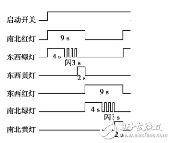
Figure 1 Traffic lights normal working sequence
1.2, emergency vehicle strong-pass timing controlWhen there is an emergency vehicle, the emergency vehicle strong switch is turned on, interrupting the original traffic light state, and the green light in the direction of the emergency traffic is illuminated until the emergency vehicle passes. When the slam car passes, the emergency switch is disconnected, and the traffic light immediately turns to the green light in the direction of the rushing car for 3 seconds, and then controls according to the normal timing. If there is a rushing car in the north-south and east-west directions, the rushing strong signal first responds to the first party and then responds to the other party.
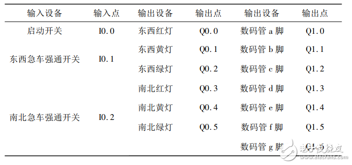
2, control system hardware designThe system adopts Siemens S7-200PLC. In order to achieve better teaching results, three kinds of light-emitting diodes of red, green and yellow are used to simulate traffic lights. The seven-segment digital display shows working time. According to the input and output points of the system, CPU226AC/DC type is adopted. PLC, a total of 24 input points, 16 output points, system I / O address definition as shown in Table 1.
Table 1 Traffic light control system I / O allocation table
Since the signal display time of the east and west directions is the same, the signal lights are connected in parallel to save the PLC output points. Considering the withstand voltage of the LED and the seven-segment digital tube, the 2kΩ resistor current limit is connected in series with the output of the PLC, and the SM4205 common cathode digital display is used for the seven-segment digital display. The corresponding hardware wiring pattern is shown in Figure 2.
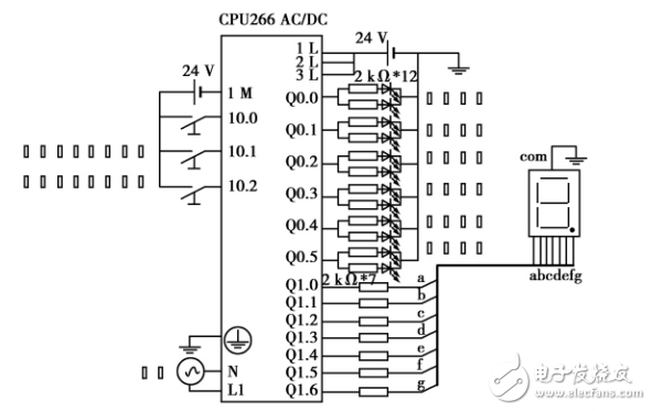
Figure 2 PLC hardware wiring diagram
3, PLC ladder diagram designThe common traffic light control program uses multiple timer designs, and the program is cumbersome and complicated. Here, a timer is used, and the time sequence of the flashing of the signal light is sequentially segmented by the data comparison command, and the flashing of the east-west green light and the north-south green light is realized by using the special memory SM0.5. Use the SEG instruction to decode the time to the seven-segment display. Interlock and strong signal end flags are implemented with 4 bit memories. The program is simple, clear and easy to understand. The ladder program is shown in Figure 3.
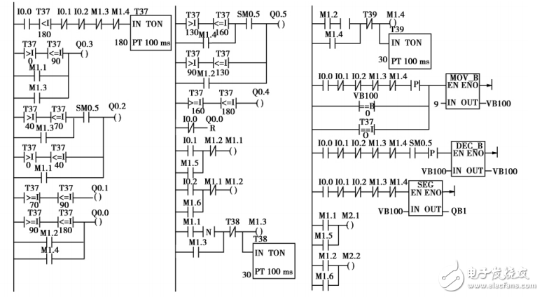
Figure 3 Traffic Light PLC Ladder Diagram
Mpo Fanout Patch Cord,Mpo-Lc Duplex Hybrid Cable,Double Sheath Hybrid Cable,Duplex Om4 Hybrid Cable
ShenZhen JunJin Technology Co.,Ltd , https://www.jjtcl.com