Every power engineer knows and learns about traditional control topologies such as voltage mode and current mode control, but does not know much about hysteresis based topologies and their advantages. While pure hysteresis control may not be practical for specific applications such as medical or industrial automation, many of the newer power supply topologies are based on hysteresis and have additional features designed to overcome the drawbacks of pure hysteresis control. Such topologies are used in a wide range of applications, from processor core power to automotive systems.
Almost all power supplies are designed to provide a stable output voltage or current. Providing this output regulation requires a closed loop system and feedback of the output voltage or current to be regulated. Although there are many different control topologies for compensating for available feedback loops, they can generally be classified into two categories: pulse width modulation (PWM) or hysteresis. Based on these two basic topologies, a third topology has evolved, which is the fusion of the two: a hysteresis-based topology. These control topologies have their own advantages and disadvantages for different applications.
Voltage mode control
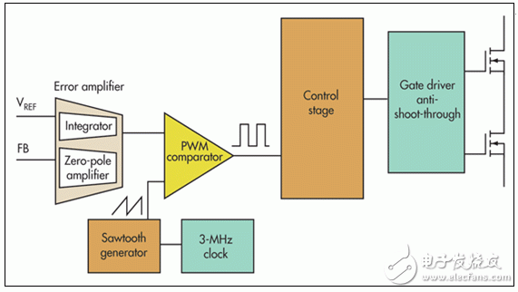
Pulse width modulation (PWM) control is classified into two basic types: voltage mode and current mode. For the sake of simplicity, this article only discusses voltage mode control with input voltage feedforward. For a more detailed comparison of voltage and current modes, see Reference 1. Figure 1 shows a basic block diagram 2 of voltage mode control in a buck converter.

Figure 1: Voltage mode control includes error amplifier, clock, and internal reference voltage (VREF)
When voltage mode control is used to regulate the output voltage, it detects a reduced version of the output voltage through a resistive divider connected to its feedback (FB) input. An error amplifier with high gain then compares the FB signal to a high accuracy internal reference voltage. The loop compensation circuit around the error amplifier is responsible for keeping the system stable.
Voltage mode control has many advantages. The topology is highly resistant to noise by adjusting only the output voltage and other well-controlled internal signals such as the clock and internal reference. And it's quite straightforward. The use of input voltage feedforward maintains simplicity to maintain a constant loop gain over varying input voltage conditions. In addition, input voltage feedforward can significantly improve response to line voltage transients. Finally, the clock implements control of the switching frequency, including the possibility of synchronizing the circuit to an external clock source.
The main disadvantage of voltage mode control is the necessary loop compensation and corresponding loop bandwidth limitations. By its very nature, voltage mode control introduces a double pole in the power stage that is at the corner frequency of the output filter, thus requiring two correctly positioned zeros to be placed around the error amplifier. Since the frequency of this double pole is usually very low, the loop bandwidth is limited to a lower level. In general, it is limited to no more than 1/10 of the switching frequency. This has a significant negative impact on the transient response of the power supply. Therefore, designers must increase output capacitance to achieve better transient results, resulting in higher system cost.
Given the trade-offs of the above advantages, voltage mode control is still valuable, especially in noise-sensitive applications. The high noise tolerance of voltage mode control and its ability to be synchronized to a system clock make it ideal for noise most sensitive applications such as medical and instrumentation.
Hysteresis control
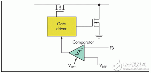
Pure and basic forms of hysteresis control are extremely simple - the simplest of all control topologies (Figure 2)3. A comparator with some small hysteresis between its terminals compares the output voltage directly to the high-accuracy internal reference voltage VREF through the FB input.

Figure 2: Simple hysteresis control topology requires only one comparator and internal VREF
The advantage of this direct control of the output voltage is the speed of the control loop. When the output voltage changes due to transients, the time required for the control loop to begin reacting is limited only by the propagation delay in the comparator and gate drivers. The error signal does not have to pass through the low bandwidth error amplifier. Therefore, the hysteresis topology is the fastest control topology.
In addition, the simplicity of its working principle allows it to maintain inherent stability without any loop compensation. And this simplicity makes it a low-cost topology. There are no oscillators or error amplifiers in the power supply that need to be designed, built, and tested. Only one basic comparator is required to control the switching action.
The main drawback of the hysteresis topology is its switching frequency variation. There is no clock or sync signal responsible for setting the switching frequency. Instead, the switching frequency is set by the amount of hysteresis as well as external components and operating conditions.
When a pure hysteresis converter is used, it is expected that a large frequency change will occur within the input voltage and load range. Moreover, if a high gain error amplifier is not used, the DC set point of the output voltage achieved may not be as accurate as when using voltage mode control. Finally, hysteresis control requires the use of equivalent series resistance (ESR) in the output capacitor. Therefore, when using a pure hysteresis topology, it is generally not possible to use a ceramic output capacitor with a very small ESR.
However, in some low-power, very low-cost applications (such as toys), the price of such terminal equipment is very low, and its low power generates electromagnetic interference (EMI) in the wide switching frequency range of the hysteretic power supply. The level is very low, so a hysteretic converter may be acceptable. In addition, systems with very harsh transients require hysteresis or hysteresis-based topologies to maintain acceptable output voltage regulation. If the input voltage, output voltage, and other operating conditions of these systems are in a well-controlled state, the switching frequency is maintained within an acceptable range. This makes hysteresis control an effective choice for applications that rely on a fixed input voltage to operate and produce a fixed output voltage.
Hysteresis based control
Many control topologies are fundamentally hysteretic, but they include other circuits designed to overcome frequency variations and other purely hysteretic topology limitations. For example, they include D-CAP, D-CAP2, COT, COT with ERM, and DCS-Control topology. This article only analyzes and compares DCS-Control 4 and similar devices.
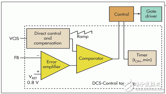
Fundamentally, DCS-Control (direct control with seamless transition to energy-saving mode) is a hysteretic topology, but it combines some of the characteristics of voltage and current modes (Figure 3). As in voltage mode control, the hysteresis comparator compares the output of an error amplifier to a sawtooth waveform.

Figure 3: In a hysteresis-based DCS-Control topology, the error amplifier and internal VREF are the same as in voltage mode control, while the hysteresis comparator is taken from a hysteresis topology. On TImer is unique to hysteresis-based topologies
The sawtooth wave is not generated from a certain clock, but is generated on the VOS input pin by a special circuit that is directly connected to the output voltage. In essence, the hysteresis comparator still has a direct connection to the output voltage through the VOS pin and is connected to a high gain error amplifier to provide very good output voltage set point accuracy.
In addition to combining hysteresis comparators from error hysteresis and voltage mode topologies with error amplifiers, DCS-Control also uses an on-time circuit to control the switching frequency. Finally, the necessary loop compensation function circuitry is built in for stability.
The main advantage of DCS-Control is that it maintains the very fast transient response of the hysteretic converter and the output voltage accuracy of the voltage mode converter, while overcoming other key defects in both topologies: slow response time, limited Control loop bandwidth and frequency changes.
Since the VOS pin provides direct control of the output voltage, any change in the output voltage will propagate directly through the control loop without being limited by the error amplifier bandwidth. This will greatly speed up the transient response.
In the current DCS-Control implementation, the main drawback is the inability to synchronize to a single clock. As a hysteresis-based topology, it does not provide a clock input signal, but instead provides a controlled switching frequency that varies minimally under various operating conditions. In some cases, this change is less than the clock frequency tolerance of the voltage mode converter.
The best use cases for hysteresis-based topologies such as DCS-Control are those that experience large transients and require extremely high output voltage accuracy. Such applications include powering processor cores in embedded or computing systems, as well as industrial automation and automotive infotainment systems.
in conclusion
For different applications, the three main power control topologies, "voltage mode", "hysteresis" and "hysteresis based", have their own advantages and disadvantages. While most power engineers are accustomed to and willing to use voltage mode control, hysteresis and hysteresis-based topologies provide best-in-class transient response and should be used for applications such as processor cores that require such fast response speeds. It does an in-depth exploration. Since each control topology has an extremely large number of devices in use, it means that for almost all applications it is possible to have an optimal power solution.
Motor Wire
We supply variety of output lead wire for motor and motor wiring harness. With the properties of chemical erode resistance, excellent bendability in high and low temperature environment and impregnating varnish erode resistance even at 302°F (150°C), this kind of wire also can bear high temperature of 392°F (200°C) with FEP and silicone rubber insulations. All of our wires and cables are UL, RoHS and REACH complaint such as UL1430, UL3266, UL3122 and UL1332 etc.
Motor Wire,Single Phase Motor Wiring,Dc Motor Wiring,Motor Lead Wire
Feyvan Electronics Technology Co., Ltd. , https://www.fv-cable-assembly.com