As people's integration requirements for communication quality and communication equipment continue to increase. As a sub-component of the communication device, the antenna also needs higher performance to meet the needs of the communication system. Up to now, various forms of antennas have been developed and applied. Yi-Chieh Lee et al. proposed an open-loop slot antenna that can operate in both 2.4 GHz and 5.2 GHz bands. Johanna M Steyn, Johan Joubert and Johann W Odendaal showcased a DBDP (Dual-Band Dual-Polarized) antenna array operating in the 2.4 GHz and 5.2 GHz bands. Zhang QY, Chu QX, Wang Y proposed a patch antenna with an integrated balun covering three frequency bands in a WLAN system. Li X, Yang L, Gong SX, and Yang YJ proposed a dipole antenna with symmetric slots on the two arms of the dipole, allowing the antenna to operate in three frequency bands. There are also other forms of antennas, such as logarithmic antennas, quasi-Yagi antennas and other forms of antennas. These antennas are either too large in size, inconvenient to integrate and conformal, or inconvenient to manufacture due to the complexity of the structure. The printed dipole antenna with coupled feed is a very simple structure and easy to conform to the antenna, suitable for communication terminals.
This article describes a printed dipole antenna that can be used in WLANs, with a balun-coupled feed 40 nnn & TImes; 50 mm size, very simple structure, covering two frequency bands of WLAN (2.4 GHz and 5.8 GHz) For WLAN systems.
1 antenna structureAccording to the working principle of the dipole, the length of the resonant arm is about 1/4 of the resonant wavelength. In order to be able to work in dual frequency, it is necessary to have a surface current that can excite two resonances. For a dipole, two pairs of resonant arms are required. In order to reduce the size of the antenna, it is generally adopted to bend the resonant arm to lengthen the current length to reduce the length of the antenna resonant arm. For the two bands of the WLAN 2 400 ~ 2484 MHz and 5 725 ~ 5 825MHz. According to the working principle of the dipole, the resonant current length corresponding to the low frequency band f0=2.4 GHz is about 31 mm, and the resonant current length corresponding to the high frequency band f0=5.8 GHz is about 13 mm. In addition, the feeding mode directly affects whether the antenna is suitable for integration or conformality. The reasonable feeding mode can not only reduce the size of the antenna, but also make the antenna easier to integrate and conformal, occupying less space in the entire communication system. . Li Feng, Zhang Fushun, and Jiao Yongchang's printed dipoles use an integrated balun to make the antenna suitable for integration and conformality. According to the above design theory, the antenna feed introduced in this paper adopts an integrated balun coupled from the back of the antenna, and the slot on the resonant arm of the antenna enables the antenna to work in dual frequency. The antenna is a WLAN that can cover the WLAN. Small dual-frequency printed dipoles in both high and low bands.
The structure of the small dual-frequency printed dipole antenna is shown in Figure 1. The entire system consists of a pair of slotted dipoles, balun feeds and dielectric plates. The dielectric plate is an FR4 dielectric plate having a thickness h = 1.0 mm and a relative dielectric constant εr = 4.4.
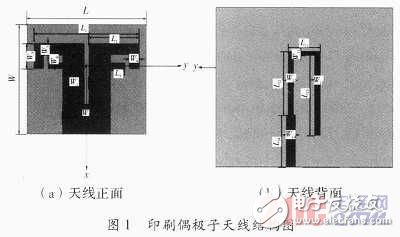
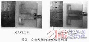
The antenna arm is opened 1 slot along the y axis, and then 1 slot is opened along the x axis to meet the requirements of the WIAN dual frequency. Since the distance between the two resonant arms is relatively close, the resonant frequency is very sensitive to the width variation of the two slots. Through continuous simulation optimization, they are determined to have widths of 3 mm and 2 mm, respectively. The width of the feeding microstrip line affects the matching of the whole antenna system, and the position of the feeding and feeding of the antenna to the antenna also affects the excitation frequency and system matching. The antenna is modeled, simulated and optimized with the commercial software Ansofi HFSS. After that, the size (unit: mm) of the antenna is obtained as L=50, L1=44, L2=21, L3=6, L11=9, L12=16, L13=21, L14=13, W=40, W1= 2, W2=20, W3=9, W4=4, W5=4, W6=3, W11=1, W12=1.5, W13=1.5, W14=2.5. The front and back structure of the processed antenna is shown in Figure 2.
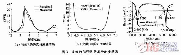
The VSWR simulation and measurement results of the antenna are shown in Figure 3(a). The impedance bandwidth of the standing wave ratio VSWR ≤ 2 is about 650MHz (2.16~2.8GHz about 26.26%) in the 2.4GHz band. The simulation result is 580MHz (about 2.377% from 2.15 to 2.73 GHz). Bandwidth, the measurement in the 5.8 GHz band is approximately 870 MHz (approximately 15.47% from 5.19 to 6.06 GHz) and the bandwidth is 850 MHz (approximately 15.1% from 5.2 to 6.05 GHz) The simulation results are similar, covering the frequency bands required by IEEE802.1l b/g (2.4 to 2.484 GHz) and IEEE802.11a (5.725 to 5.825 GHz), from the comparison of simulation results and measurement results. Look, in general, it is quite consistent. The inconsistency in the low frequency band should be caused by the numerical calculation error of the simulation software.
When the antenna is operating in the 2.4 GHz band, the radiating has a long resonant arm. At this time, the length of the current along the long arm is about 30 mm, which is very close to 1/4 of the operating wavelength of the band. When the antenna is operating in the 5.8 GHz band, the radiation is generated by a short resonant arm. The current along the short arm is about 14 mm and is very close to 1/4 of the operating wavelength of the band. The simulation results are in line with the theoretical expectations before slotting, so the slotting of the dipole arm in the manner described in the text can make the antenna work in dual frequency and meet the bandwidth requirements of the WLAN.
Three Phase Isolation Transformer
Introduction:
Three phase dry type isolation transformer is a new generation of energy-saving power transformer developed by our factory from 300VA to 1600KVA on the basis of international similar products and in accordance with international and national standards such as IEC439 and GB5226. The winding adopts hole array winding. Vacuum impregnation is adopted for the transformer to make the insulation level of the transformer reach F or H, and the product performance reaches the advanced level at home and abroad. SG series three-phase dry type isolation transformers are widely used in circuits with AC 50Hz to 60Hz and voltage lower than 2000V. All these can be customized according to the different requirements of the end user.
Normal service conditions:
1. The altitude shall not exceed 2500M
2. Ambient medium temperature: ≥ - 25 ℃, ≤+40 ℃
3. Current and voltage waveforms are similar to sine waves.
4. No rain and snow erosion, no obvious shaking and impact vibration at the installation site.
5. No explosion hazard, gas and conductive dust.
Three Phase Isolation Transformer,Industry Auto Transformer,Transformer 220V To 380V,10Kva Transformer 3 Phase
Henan New Electric Power Co.,Ltd. , https://www.newelectricpower.com