RFID technology uses wireless radio frequency for non-contact two-way communication to achieve the purpose of identifying and exchanging data. Unlike contact recognition technologies such as magnetic cards and IC cards, RFID tags can be identified without physical contact between the electronic tag and the reader, and are non-contact identification. RFID technology has some unique advantages, which can be more widely used in transportation, medical and anti-counterfeiting.
With the rapid development of China's economy, the Ministry of Railways has invested a large amount of money in the construction of an automatic identification system for all roads. The goal is to install electronic tags on all locomotives, in all section stations, marshalling stations, and large freight. The station installs the ground reading and writing device to accurately identify the running train and vehicle information. Railway radio frequency number automatic identification system has become an important part of railway information construction. The TKCG-08RFID train automatic identification system was developed under this background. It uses microwave radio frequency communication technology to realize automatic identification of train number.
Data transmission is an important part of the operation of RFID systems. The RF signal is transmitted through the spatial coupling (alternating magnetic field or electromagnetic field) of the reader antenna and the tag antenna. Therefore, the antenna plays an important role in the entire RFID system. On the one hand, the quality of the antenna determines the communication quality of the system, and On the one hand, the antenna determines the communication distance of the system.
Depending on the operating frequency band, different types of antennas are used in RFID products, and there are many types of antennas to choose from. At the time of selection, antenna size, cost, and performance are all very important factors. The three most common short-range antenna devices are PCB microstrip antennas, chip antennas, and whip antennas with a connector. The application of TKCG-08 subway train identification system is mainly to install the reader in the middle of the track, and the RF card is installed in the corresponding position in the lower part of the car body, as shown in Figure 2. When the train passes the reader at a certain speed, the reader recognizes the corresponding card number of the radio frequency card, and then obtains the train number information. Due to the limited size of the RF card and the need to control the cost, the microstrip antenna has the advantages of low cost, high performance, small size, etc. Therefore, the microstrip antenna is selected as the antenna form used in the system.
Microstrip antennaA microstrip antenna is an antenna formed by attaching a conductor sheet to a dielectric substrate having a conductor ground plate. It uses a feeder line such as a microstrip line or a coaxial line to feed the RF electromagnetic field between the conductor patch and the ground plate, and radiates outward through the gap between the patch and the ground plate, so the microstrip antenna can be regarded as It is a slot antenna, as shown in Figure 3. Compared with the commonly used microwave antenna, it has the following advantages: small size, light weight, low cost, and the feed network can be made with the antenna structure, suitable for mass production by printed circuit technology, and with active devices and The circuit is integrated into a single module, which is easy to obtain circular polarization, and is easy to implement dual-frequency, multi-band operation.
The patch conductors can be designed in a variety of shapes depending on the radiation characteristics of the antenna. Usually, the radiation conductor of the patch antenna is separated from the metal base plate by a wavelength of a few tenths of a wavelength. Assuming that the radiated electric field does not change along the transverse and longitudinal directions of the conductor, only along the length of the conductor of about half a wavelength, the radiation of the microstrip patch antenna is substantially caused by the fringe field of the open edge of the patch conductor. The direction of radiation is basically determined.
The microstrip antenna facilitates the selection of a suitable feeding position to make the radiating element and the feeding line are well matched, and has a small volume profile and good electrical performance, and achieves one-dimensional miniaturization. Based on this miniaturized antenna, a microstrip antenna is used. The micro-band antennas achieve circular polarization feeding methods mainly include: doubly-fed point feeding and single-feed point feeding. Each of the feeding methods can adopt various feeding modes such as direct feeding, slot coupling feeding, and probe feeding. The single-feed point method of direct feeding does not need to design any complicated phase-shifting network and power distribution to realize circularly polarized radiation. It is a simple method to realize circular polarization, so it is generally fed by single-feed point direct feeding. .
Microstrip antenna designAccording to the microstrip antenna theory, the size of the patch unit width W directly affects the directivity function, the radiation resistance, and the input impedance of the microstrip antenna. Considering that both radiation efficiency and high-order modes are avoided, the width W is usually required to meet the requirements of equation (1):
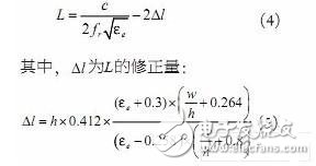
Where h and w are the height and width of the antenna, respectively. However, in the actual design, the influence of the fringe field should be considered, and the L value should be corrected, so L is determined by the formula (4):
Because the electric field is non-uniformly distributed along the L direction, the impedance of the feed point can be changed by changing the position of the coaxial feed point in the L direction to achieve the matching state of the signal. The admittance of the feed point position is shown in equation (6):
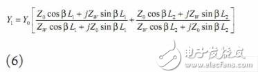
Where Z0 is the characteristic impedance when the antenna is regarded as the transmission line; Y0 is its corresponding admittance; ZW is the wall impedance; β is the phase constant in the medium; L1 and L2 are the feeding points in the L direction to the edge of the radiation electrode respectively distance. By changing the size of L1 and L2, the input impedance can meet the requirements of impedance matching.
The design must also take into account the length and width of the radiation electrode L, W to meet the necessary conditions for the circular polarization of the rectangular patch antenna, namely:
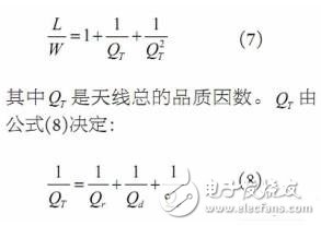
Where Qr, Qd, Qe correspond to the Q values ​​of radiation, dielectric and conductor losses, respectively.
Super D Temper Glass Screen Protector
This TEMPERED GLASS SCREEN PROTECTOR is chemical processed real glass, it features high transparency, high sensitivity and delicate touch feeling. The premium tempered glass has an oleophobic coating that prevents contaminants. Big curved edges provides full coverage over the screen. Secure shatterproof function, will not be broken into small pieces of sharp. This tempered glass screen protector is chemical processed real glass, it features high transparency, high sensitivity and delicate touch feeling. The premium tempered glass has an oleophobic coating that prevents contaminants. Big curved edges provides full coverage over the screen. Secure shatterproof function, will not be broken into small pieces of sharp. This tempered glass screen protector is chemical processed real glass, it features high transparency, high sensitivity and delicate touch feeling. The premium tempered glass has an oleophobic coating that prevents contaminants. Big curved edges provides full coverage over the screen. Secure shatterproof function, will not be broken into small pieces of sharp.
Screen Protector,super D screen protector
Mietubl Global Supply Chain (Guangzhou) Co., Ltd. , https://www.mietublmachine.com