With the continuous development of semiconductor materials and processes, the output power of microwave/millimeter wave power semiconductor devices is increasing in magnitude, and the pulse power of L-band power transistors has reached the order of kilowatts; X-band power GaAs FETs are continuous The wave reaches tens of watts and the pulse power reaches 500W. However, limited to the physical characteristics of semiconductors, the output power of a single solid state device is still limited. The power synthesis technology of chip synthesis, circuit synthesis and spatial synthesis is used to superimpose the output power of multiple solid-state devices in phase, which is one of the effective ways to obtain higher output power.
In 1968, Josenhans first proposed the concept of chip-level power synthesis. Then, in the late 1970s, Rucker first implemented multi-chip circuit power synthesis in the X-band and extended it to 40 GHz. In 1999, KohjiMatsunag, IkuoMiura, and Naotaka lwata used the MM IC multi-chip synthesis technology to design a Ka-band power amplifier chip with four independent MM ICs, and obtained 3 W in the frequency range of 26.5 to 28.5 GHz. Continuous wave output power.
In this paper, the research of power synthesis circuit based on microstrip Wilkinson power splitter is carried out, and a Ku-band 1 W power amplifier is realized. In applications such as satellite communications, the power amplifiers required are in the order of tens of watts to hundreds of watts. Obviously, this power level amplifier cannot be directly used as a power amplifier for satellite communication, but can be widely used as a driver for high power amplifiers such as traveling wave tubes. As the basis of 2n power synthesis, the power synthesis technology involved in this paper can provide important reference value for related technical fields.
1 Overall structure and design goalsThe principle block diagram of the power synthesis circuit used in this paper is shown in Figure 1. WPD1 in Figure 1 is a Wilkinson splitter as an input power splitter, and WPD2 is another Wilkinson splitter as an output power combiner. Their structure was selected from the new structure proposed in this paper and designed using the same design method described below. The SPS in Figure 1 is a Schiffman quadrature phase shifter. The TGF2508-SM in Figure 1 is a Ku-band power amplifier chip from Triquint, USA. It has a 1 dB power compression point power of 28 dBm, a small signal gain of 25 dB, and an operating bandwidth of 12 to 17 GHz. This device is chosen as the basic component of two-way power synthesis. The theoretical maximum combined power is 31 dBm. The design goal of this paper is to use the bandwidth of TGF2508-SM as much as possible to achieve the widest possible frequency band, and the in-band synthesis efficiency is more than 70%. For this purpose, both the Wilkinson splitter and the Schiffman quadrature phase shifter must have the same bandwidth as the TGF2508-SM. Subordinate research in this paper achieves this goal.
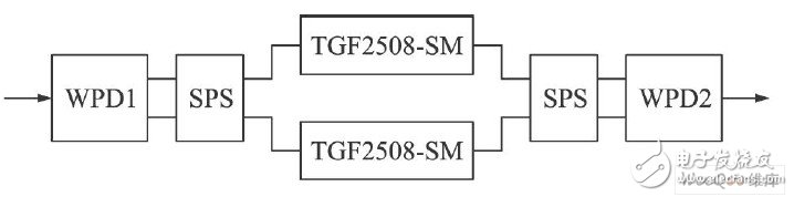
Figure 1 is a block diagram of the power synthesis circuit implemented in this paper.
2 Wilkinson Power Splitter ImprovementFigure 2 generally shows an improvement of the Wilkinson splitter.
Figure 2a is the basic form of the Wilkinson splitter. Since an isolation resistor is required between the two outputs, and the volume of this resistor is small, the distance between the two λ/4 transmission lines in the circuit is required to be very close. Causes mutual coupling, which affects the bandwidth nature of the circuit. Due to these inherent shortcomings of the basic form of the Wilkinson splitter, when operating at frequencies above the X-band, bandwidth and other performances are no longer sufficient. The modification shown in Fig. 2b is proposed to avoid the above-mentioned disadvantages of the basic type, but also because of the isolation resistance, the distance between the two output ports is still very close, and mutual coupling cannot be avoided. The circuit shown in Figure 2c overcomes the above disadvantages, but the bandwidth performance is degraded due to the introduction of longer transmission line segments.
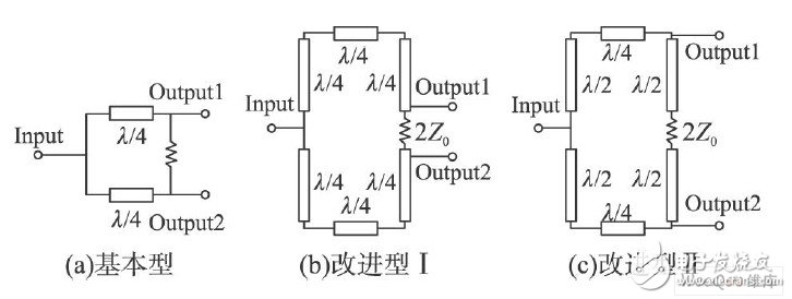
Figure 2 Evolution of the WPD structure
The circuit shown in Figure 2b is modified to the circuit shown in Figure 3a. Thereby the above disadvantages of the above basic and improved types are overcome while retaining better broadband characteristics. The microstrip layout of this circuit is shown in Figure 3b. The results of simulation of the above circuit using ADS are shown in Figure 4. The results show that the circuit has good 3 dB division performance in 12 ~ 18 GHz, which satisfies the design goals presented above.
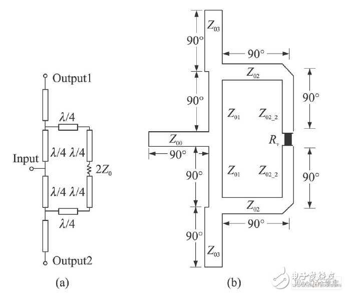
Figure 3 Schematic diagram and microstrip structure of the Wilkinson splitter used in this paper.
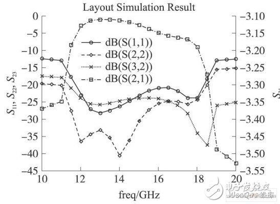
Figure 4 ADS co-simulation results of Wilkinson splitter
3 Schiffman quadrature phase shifterThis paper also implements the Ku-band quadrature phase shifter required for power synthesis. The type of phase shifter used in this paper is a dual Schiffman quadrature phase shifter. The dual Schiffman phase shifter has a slightly smaller bandwidth than the standard Schiffman phase shifter, but the coupling factor requirements are greatly reduced. The results of simulating the dual Schiffman quadrature phase shifter with ADS are shown in Fig. 5. As can be seen from Fig. 5, the phase difference between the two output section ports is between 70° and 95°. Substituting the maximum phase difference into the formula in [9]:
Barebone System Computer,Barebone Mini Pc,Mini Pc Desktop Computer,Barebone Mini Computer
Shenzhen Innovative Cloud Computer Co., Ltd , https://www.xcypc.com