5G commercial, bear first. Recently, China Telecom officially released the "White Paper on 5G Era Optical Transport Network Technology". This white paper clearly describes the future 5G bearer technology for the changes of the future 5G business and network architecture. It is worth reading. When Xiaobian is learning, he edits it out for everyone to learn.
1 5G network architecture impact on the bearer network architecture
1.1 5G separated RAN architecture
Compared with the BBU and RRU two-level architecture of the 4G LTE access network, the 5G RAN will evolve into a three-level structure of CU, DU and AAU.
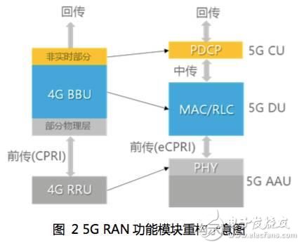
CU: The non-real-time part of the original BBU will be split and redefined as a CU (Centralized Unit), which is responsible for handling non-real-time protocols and services.
AAU: Part of the physical layer processing function of the BBU is merged with the original RRU into an AAU (Active Antenna Unit).
DU: The remaining functions of the BBU are redefined as DU (Distribute Unit), which is responsible for processing physical layer protocols and real-time services.
Thus, after the RAN is separated, the bearer network is divided into three parts: preamble, middle pass and back pass.
Frontanul: between AAU and DU.
Middlehaul: between DU and CU.
Backhaul: CU or above.
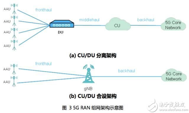
Among them, there is a 5G deployment similar to 4G, which adopts the combination of CU and DU, only the pre-transmission and the back-transmission, mainly to reduce the delay, as shown in Figure (b) above.
1.2 Core network clouding and sinking
In order to meet the flexibility and low latency of 5G networks and reduce the burden of backhaul, the core network sinking and clouding become an inevitable trend, and MEC (Mobile Edge Computing) is introduced to form a more distributed architecture.
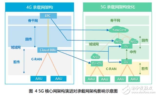
The original EPC is split into two parts: New Core and MEC: New Core will be deployed in a large data center at the core of the metro, and the MEC will be deployed in a small or medium-sized data center in a metropolitan area or a lower location. The interconnection requires the bearer network to provide a flexible Meshed DCI (Data Center Interconnect) network for adaptation.
The MEC will share more core network traffic and computing power, and its number will increase. Different services may be backhauled to different clouds. Therefore, the bearer network needs to provide routing and forwarding capabilities for different services to be categorized by different CUs to different MECs. The connection established between the original base station and each EPC also evolved into a connection relationship between CU to cloud (MEC) and cloud to cloud (MEC to New Core).
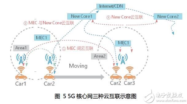
As shown in the figure above, the three categories of 5G core cloud interconnection include:
(1) Inter-MEC interconnection: including MEC interaction traffic caused by terminal mobility, MEC change of the UE, V2X and other applications, such as V2X, the traffic that interacts with the original MEC, and the user-to-user MEC traffic.
(2) MEC and New Core interconnection: including MEC unmatched service and New Core interaction traffic, New Core and MEC control plane interaction traffic, MEC edge CDN return source traffic.
(3) Interconnection between New Core: embodied as part of the interconnection traffic between the core cloud DCs.
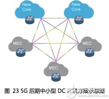
Based on the above-mentioned network interconnection requirements between MEC and NewCore, the core network moves down to form a two-layer cloud interconnection network, including: the core cloud Internet formed between New Core and New Core and MEC, and the edge cloud Internet formed between MECs. Among them, the small and medium-sized data center at the edge will undertake functions such as edge cloud computing and CDN, as shown in the following figure.

2 5G bearer network needs analysis
2.1 Large bandwidth requirements
Due to the adoption of high frequency bands, wider spectrum and new air interface technology, the bandwidth demand of 5G base stations has increased significantly, and it is expected to reach 10 times of LTE. The following table shows the bandwidth demand estimates for a typical 5G single S111 base station:

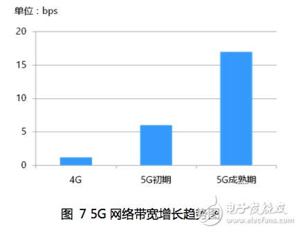
Take a large metropolitan area network as an example. The number of 5G base stations is 12000, and the bandwidth convergence ratio is 6:1. The bandwidth requirements of the core layer will exceed 6T in the initial stage and the maturity will exceed 17T. Therefore, the access and aggregation layer of the 5G transmission bearer network needs to introduce a 25G / 50G rate interface, while the core layer needs to introduce an interface of 100G and above.
2.2 Low latency requirements
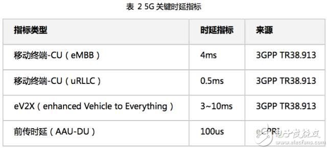
Relevant technical indicators of 3GPP delays such as 3GPP and related standards organizations are shown in the following table.
In order to meet the requirements of 5G low latency, the optical transport network needs to further optimize the device delay and networking architecture:
1) In terms of device delay: you can consider using larger time slots (such as increasing from 5Gbps to 25Gbps), reducing the multiplexing level, reducing or canceling the cache, etc. to reduce the device delay to 1us or lower. .
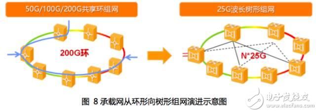
2) In terms of networking architecture, you can consider the tree network instead of the ring network to reduce the delay.
The figure below shows a typical 8-point ring. Obviously, since the ring network accumulates the transmission delay one by one, the ring network of the device requires a single node processing delay to be greatly reduced, and congestion is not guaranteed. As long as the tree-shaped networking considers the delay accumulation between the source and sink nodes, it can greatly improve the network's tolerance to severe delays.
2.3 High precision time synchronization requirements
The third key requirement for 5G bearers is high-precision clocks, which provide different clock accuracies depending on the type of service. 5G synchronization requirements include 5G TDD (Time Division Duplex) basic service synchronization requirements and coordinated service synchronization requirements.
1) From the current 3GPP discussion, the 5G TDD basic service synchronization demand is estimated to maintain the same synchronization accuracy of +/-1.5us as the 4G TDD basic service.
2) High-precision clock synchronization is beneficial to the gain of coordinated services, but the synchronization accuracy is limited by the length of the wireless air interface frame. The 1G air interface frame length is 1ms smaller than the 4G air interface frame 10ms, so the index reserved for synchronization accuracy will also be Zoom out, specific indicators have yet to be determined.
Therefore, the 5G bearer needs more high-precision synchronization: the 5G bearer network architecture must support the clock to go straight with the service, reduce the intermediate node clock processing; the single-node clock accuracy also satisfies the ns accuracy requirement; the single-fiber bidirectional transmission technology facilitates the simplified clock Deployment, reducing the asymmetric clock compensation in the receive and transmit directions, is a clock transmission technique worth promoting.
2.4 Requirements for Flexible Networking
At present, the Layer 3 device of the 4G network is generally set in the core layer of the metropolitan area backhaul network, and the Layer 2 or Layer 3 bridge setting is performed in a pairwise manner. For the inter-station X2 traffic, the path is access-aggregation-core bridging-aggregation-access. The X2 service passes through many hops and has a long distance, and the delay is often large. In the 4G era, which is not sensitive to delay and the flow rate is less than 5%, this method is more reasonable and the maintenance requirements are relatively simple.
However, some applications in the 5G era are more sensitive to delays, and the proportion of traffic between stations is increasing. At the same time, because the 5G phase will adopt ultra-dense networking, the inter-station coordination is closer than 4G, and the proportion of inter-station traffic will exceed the X2 traffic in the 4G era.
The following is an analysis of the flexible networking requirements of the backhaul and the intermediate transmission networks.
(1) Backhaul network
There are connection requirements between the CU of the 5G network and the core network (S1 interface) and between the adjacent CUs (eX2 interface). The eX2 interface traffic between the CUs mainly includes the inter-station CA (Carrier Aggregation) and CoMP. (Coordinated Multipoint Transmission/Reception, coordinated multipoint transmission/reception) traffic, which is generally considered to be 10~20% of S1 traffic. If the static connection is manually configured, the configuration workload is very heavy and the flexibility is poor. Therefore, the backhaul network needs to support IP addressing and forwarding.
In addition, in order to meet the demand for ultra-low latency in the uRLLC application scenario, a CU/DU combination method is needed, so that the bearer network has only two parts: pre-transmission and back-transmission. At this time, the bearer network of the DU/CU co-located location also needs to support IP addressing and forwarding capabilities.
(2) China Communications Network
In the initial stage of 5G network deployment, the relationship between the DU and the CU is relatively fixed. Generally, a DU is fixedly assigned to one CU. Therefore, the intermediate transmission network does not need IP addressing and forwarding functions. However, in the future, after the CU cloud deployment is deployed, the redundancy, dynamic capacity, and load balancing capabilities are required to change the affiliation between the DU and the CU. The DU needs to be flexibly connected to two or more CU pools. In this way, the intermediate transmission network between the DU and the CU needs to support the IP addressing and forwarding functions.
As mentioned above, in the 5G mid- and back-transmission bearer networks, network traffic is still dominated by north-south traffic, supplemented by east-west traffic. There is no application scenario where one DU/CU has east-west traffic with all other DU/CUs. A DU/CU only has east-west traffic with the neighboring cell's DU/CU, so the service flow is relatively simple and stable. The bearer network only needs to provide simplified IP addressing and forwarding capabilities.
2.5 Network Slice Requirements
5G networks have three main types of services: eMBB, uRLLC and mMTC. Different application scenarios have different network requirements, such as delay, peak rate, and QoS (Quality of Service). In order to better support different applications, 5G will support network slicing capabilities, and each network slice will have its own independent network resources and management capabilities, as shown in the following figure.
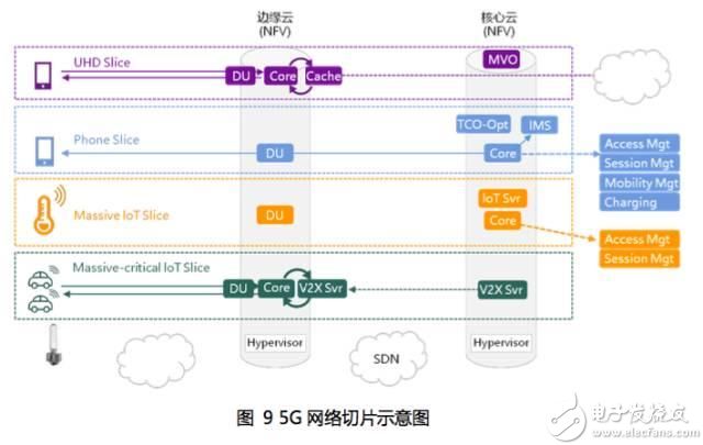
On the other hand, the physical network can be sliced ​​according to the needs of different tenants (such as virtual operators) to form multiple parallel virtual networks.
The 5G wireless network requires end-to-end network slicing from the core network to the UE, reducing the interaction between services (slices). Therefore, the 5G bearer network also needs to have a corresponding technical solution to meet the differentiated bearer requirements of different 5G network slices.
The pre-transmission network generally adopts a transparent transmission processing method for the eCPRI signal used by the 5G, and does not need to perceive the specific content of the transmission, so no special processing is required for different 5G network slices. The intermediate transmission/backhaul bearer network needs to consider how to meet the different requirements of bandwidth, delay and networking flexibility of different 5G network slices, and provides a bearer scheme for 5G network slicing.
3 5G optical transport network bearer solution
The 5G bearer network consists of three parts: pre-transmission, middle transmission, and back-transmission.
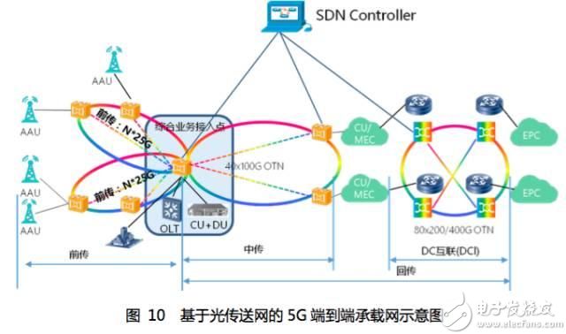
A wireless centralized device (DU or CU+DU) can be deployed at the Integrated Service Access Point (CO). The CO node bearer device can aggregate the pre-transmitted traffic to the wireless device of the node, and can also upload the intermediate/backhaul service to the upper-layer bearer device. As a comprehensive access node, the CO node requires a rich access service type and high requirements for bandwidth and delay. Packet enhanced OTN equipment can well meet the above requirements.
3.1 5G pre-transmission bearer solution
The 5G preamble is divided into three different scenarios: (a) small concentration, (b) large P2P concentration, and (c) large concentration of the ring network.
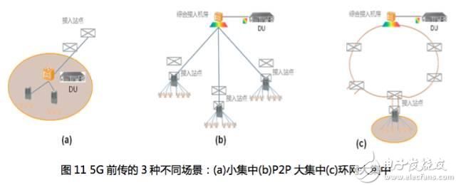
Small set: The deployment location of the DU is lower, which is basically the same as that of the 4G macro station BBU. The number of 5G AAUs connected to the DU is generally less than 30 (<10 macro stations).
Large concentration: The DU deployment location is higher and is located in the integrated access point equipment room. The number of 5G AAUs connected to the DU in this scenario is generally greater than 30 (>10 macro stations).
Further, according to the resource and topology distribution of the optical fiber and the network requirements (protection, management), the scene of the large concentration can be further subdivided into a large P2P concentration and a large concentration of the ring network.
For the three networking scenarios of 5G pre-transmission, the optional bearer technology scheme is recommended as shown in the following table:

3.1.1 Passive WDM scheme
The passive wavelength division scheme uses wavelength division multiplexing (WDM) technology to install the color light module on the wireless devices (AAU and DU), and complete the WDM function through a passive combination or splitter board or device, using a pair of even An optical fiber can provide multiple AAU to DU connections, as shown in the following figure.
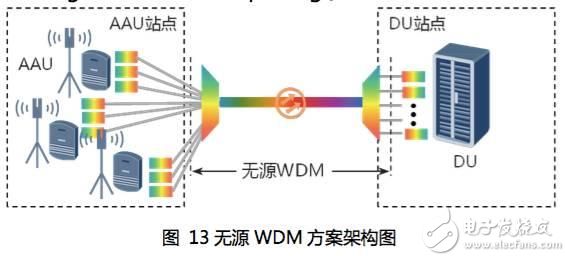
According to the wavelength attribute adopted, the passive wavelength division scheme can be further divided into a CWDM (Coarse Wavelength Division Multiplexing) scheme and a Dense Wavelength Division Multiplexing (DWDM) scheme.
Compared with the fiber direct drive scheme, the obvious benefit of the passive WDM scheme is that it saves the fiber, but it also has certain limitations, including: limited number of wavelength channels, complicated wavelength planning, difficulty in operation and maintenance, and difficulty in fault location.
After the failure of the passive WDM scheme, it is difficult to specifically delineate the responsible party of the problem. The following figure shows the fault location diagram of the passive WDM scheme, which shows the complexity of fault location.
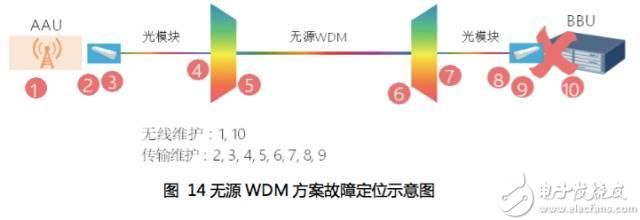
Passive DWDM schemes clearly provide more wavelengths than passive CWDM schemes. But more wavelengths also mean higher wavelength planning and control complexity, often requiring tunable lasers for higher cost. At present, passive DWDM optical modules supporting 25Gb/s rate have yet to be matured.
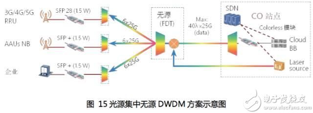
In order to meet the requirements of 5G bearer, passive DWDM scheme based on tunable wavelength is a feasible solution. In addition, a new passive DWDM scheme based on remote concentrated light source has become a hot spot in the industry. The principle is shown in the figure below. This solution has certain advantages in reducing costs, especially on the access side, and improving performance and maintenance convenience.
3.1.2 Active WDM/OTN Solution
The active wavelength division scheme configures the metro access WDM/OTN equipment in the AAU site and the DU equipment room. The multiple preamble signals pass through the common fiber fiber resources of the WDM technology, and are managed and protected by the OTN overhead to provide quality assurance.
The access type WDM/OTN device and the wireless device are connected by a standard gray optical interface, and the WDM/OTN device internally performs functions such as OTN bearer, port aggregation, and color light zoom. Compared with the passive wavelength division scheme, the active wavelength division/OTN scheme has a more free networking mode and can support two scenarios: point-to-point and group ring network:
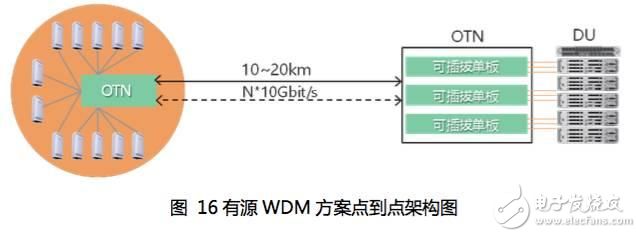
The figure above shows the point-to-point networking architecture of the active solution. It can also support single-fiber unidirectional, single-fiber bidirectional transmission modes. Compared with the passive division scheme, the fiber resources consumption is the same.
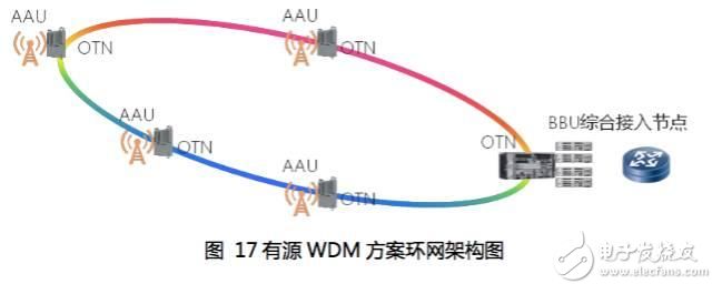
The figure above shows the architecture of the active solution group ring network. In addition to saving fiber accidents, the active WDM/OTN solution can further provide functions such as ring network protection to improve network reliability and resource utilization.
Current active WDM/OTN solutions are relatively costly and can be reduced in the future by using non-coherent overclocking techniques or low cost pluggable optical modules. At the same time, in order to meet the needs of 5G forward low cost and low latency, OTN technology needs to be simplified.
3.2 5G transmission/return bearer scheme
According to the previous requirements analysis, the 5G intermediate transmission and the backhaul have basically the same requirements for the bearer network in terms of bandwidth, networking flexibility, network slicing, etc., so a unified bearer scheme can be adopted.
3.2.1 Intermediate/Return Bearer Network Architecture
The metro OTN network architecture includes the backbone layer, the aggregation layer, and the access layer, as shown in the following figure.
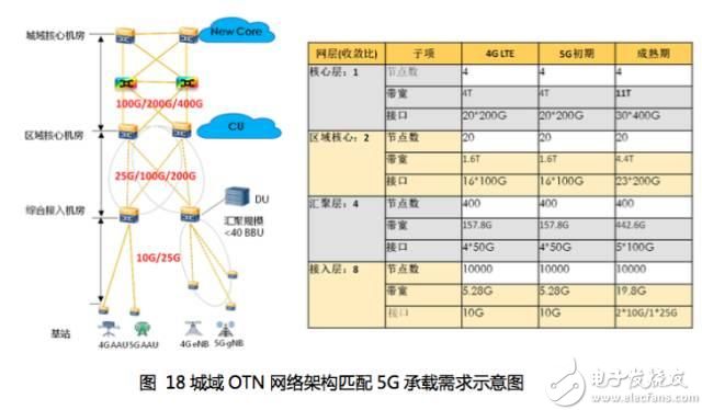
The metropolitan area OTN network architecture is matched with the bearer requirements of the 5G transmission/retransmission. The backbone layer/aggregation layer corresponds to the 5G backhaul network, and the access layer corresponds to the intermediate transmission/previous transmission.
In recent years, OTN has evolved to packet-enhanced OTN by introducing packet switching and processing capabilities such as Ethernet, MPLS-TP (Multiprotocol Label Switching Traffic Policing), which can match 5G IP well. Carrying demand.
The OTN-based 5G transmit/return bearer solution can utilize the powerful and efficient frame processing capability of the packet enhanced OTN through FPGA (Field Programmable Gate Array), dedicated chip, DSP (Digital Signal Processor, digital signal). Special hardware such as processing) performs fast framing, compression decompression, and mapping functions, effectively implementing functions that are extremely sensitive to latency requirements such as MAC/PHY in the air transmission connection.
At the same time, for the CU, on the one hand, the packet enhanced OTN constructs a connection between the CU and the DU with a large bandwidth and an ultra-low delay, effectively realizing the real-time, efficient and reliable PDCP processing, and supporting fast signaling access. The packet-enhanced OTN integrated WDM capability enables long-distance transmission to suburban counties and increases the bandwidth capacity of the transmission link as needed.
In order to meet the requirements of the medium transmission/retransmission in the flexible networking, it is necessary to consider the enhancement of the routing and forwarding function on the basis that the packet enhanced OTN already supports the MPLS-TP technology.
The OTN-based 5G transmission/return bearer scheme can be subdivided into the following two networking modes:
(1) Packet enhanced OTN+IPRAN scheme
In this solution, the packet-enhanced OTN device with the enhanced route forwarding function is used to set up the intermediate transmission network. The intermediate OTN device can be configured as an ODUk punch-through mode as required to ensure the low-latency and bandwidth guarantee requirements of the 5G bearer. In the backhaul part, the existing IPRAN (IP Radio Access Network) bearer architecture is continued, as shown in the following figure. The packet enhanced OTN and the IP RAN exchange routing information through the BGP protocol.
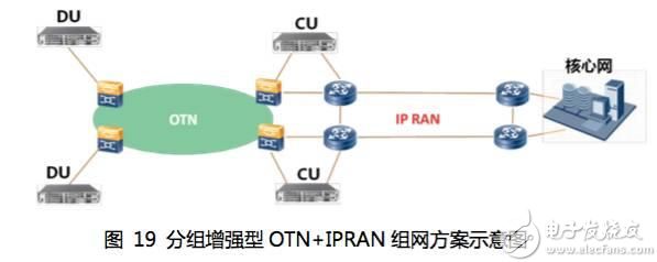
In order to meet the load requirements of 5G bearers for large capacity and network slicing, IPRAN needs to introduce high-speed interface technologies such as 25GE, 50GE, and 100GE, and consider adopting new interface technologies such as FlexE (Flexible Ethernet) to achieve physical isolation and provide better. The quality of the bearer is guaranteed.
(2) End-to-end packet enhanced OTN solution
The solution is implemented by a packet-enhanced OTN device with enhanced routing and forwarding functions, as shown in the following figure.
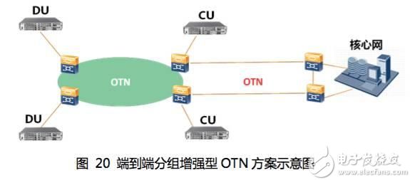
Compared with the packet-enhanced OTN+IPRAN scheme, this scheme can avoid the problem of interworking and inter-professional coordination between packet-enhanced OTN and IPRAN, so as to better utilize the powerful networking capabilities and end-to-end maintenance of packet-enhanced OTN. Management ability.
3.2.2 Network Slice Bearer Solution
In essence, network slicing is the division of network resources. The optical transport network has a natural network slice carrying capacity, and each 5G network slice can be carried by an independent optical wavelength/ODU channel, providing strict service isolation and quality of service guarantee. Specific to the bearer requirements of 5G network slices, the packet enhanced OTN can provide one-layer and two-layer network slice bearer schemes.
(1) Based on a layer network slice bearer scheme
The network resources are divided based on the ODUflex. Different ODUflex bandwidths can be divided by channel identifiers to carry different 5G network slices, and the bandwidth of the ODUflex can be dynamically and non-destructively adjusted according to the change of service traffic. You can also use the physical port to divide the bearer resources. You need to isolate all the electrical layer links corresponding to the physical port. The implementation is simple and the granularity is large.
(2) Based on the Layer 2 network slice bearer scheme
The solution is to isolate the bandwidth of the Layer 2 port by using an MPLS-TP label or an Ethernet VLAN ID (Virtual Local Area Network). Different logical channels are used to carry different 5G network slices, and the QoS control strategy is adopted to meet the performance requirements of bandwidth, delay and packet loss rate of different network slices.
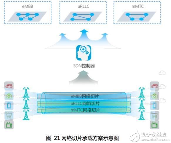
The inter-slice services of the layer network bearer bearer scheme are physically isolated and do not affect each other. The inter-slice service of the Layer 2 network slice bearer scheme is logically isolated, and services between different slices can share physical bandwidth. Different bearer schemes can be selected according to the performance requirements of 5G different network slices.
The OTN network slice bearer solution can be combined with SDN (Software-defined Networking) intelligent control technology to implement fast end-to-end configuration and management of network resources, improve network resource usage efficiency, and improve service provisioning efficiency and network maintenance efficiency. . And by opening the northbound interface, the VRNS (Virtual Transport Network Service) is used to provide the upper layer 5G network with the ability to control the optical transport network resources, as shown in the following figure.
3.3 5G Cloud Data Center Interconnection Solution
As mentioned above, the core network of the 5G era has moved down and transformed into a cloud-based architecture, resulting in the need for cloud data center interconnection, including: (1) core large data center interconnection, corresponding to 5G core network New Core and New The connection between Core and MEC; (2) The interconnection of small and medium-sized data centers on the edge, and the local DC interconnection assumes functions such as MEC and CDN.
3.3.1 Large Data Center Interconnection Solution
As an important part of the New Core core network in the 5G bearer network, the large data center bears the long-distance interaction function of massive data, and requires high-reliability long-distance transmission, minute-level service provisioning capability, and large-capacity wavelength-level interconnection. Therefore, it is necessary to use a high-latitude ROADM to perform meshing networking and direct optical layer hopping, thereby reducing the cost of the intermediate large-capacity service electrical punch-through port. At the same time, it is also necessary to combine OTN technology and 100G, 200G, 400G high-speed coherent communication technology to achieve high-capacity high-speed interconnection between core DCs, and is compatible with various particle flexible scheduling capabilities.
The protection of the security of the network is ensured by the optical layer and the electrical layer. The protection effect and the configuration of the protection resources are optimized. The WSON (Wavelength Switched Optical Network) is implemented in the existing optical layer path through the ROADM. The route is resistant to multiple fiber breaks and no additional board backup is required. The Automatically Switched Optical Network (ASON) can quickly switch the protection path through OTN electrical cross backup. The protection time is <50ms.
3.3.2 Small and medium data center interconnection scheme
With the development of 5G, small and medium-sized data center interconnection solutions can be considered to evolve according to the following three stages:
(1) In the early stage of 5G, the edge interconnection traffic was small, but the types of access services were numerous and the granularity was diversified. It can make full use of the low-latency, high-reliability interconnection channel provided by the existing packet-enhanced OTN network, and use the ODUk-level interconnection method. At the same time, the packet-enhanced OTN can well integrate the OTN hard pipe and packet characteristics to meet the requirements of diversified edge DC access services.
(2) In the middle of 5G, the local service traffic is gradually increased. It is necessary to combine the optical layer ROADM to perform mesh interconnection between edge DCs based on the packet enhanced OTN interconnection. However, due to the small number of link dimensions, it is suitable to use low-dimensional ROADM, such as 4D or 9D. Considering the scale of the edge calculation and the cost of moving down, the DCI network is divided into two layers. The core DCI layer and the edge DCI layer have a certain number of connections between the two layers.
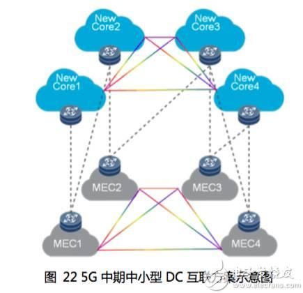
(3) In the late 5G, network data traffic is huge, and business scheduling needs to be performed within the entire network. In this case, a large number of high-latitude ROADMs (such as 20-dimensional or even 32-dimensional next-generation ROADM technologies) need to be deployed across the entire network to implement all-optical connections between edge DCs and core DCs to meet the low latency requirements of services. At the same time, OTN is used to realize the aggregation and exchange of small granular services.
3.4 Summary of 5G Optical Transport Network Bearer Solution
The 5G bearer network is a comprehensive bearer network with the convergence of mobile/broadband/cloud leased line architecture. It needs to have the capacity of 10G~100G bearer and 1~2 times of site bandwidth evolution, very low latency, high precision clock architecture, and support mobile & The dedicated line & broadband integrated bearer has flexible evolution capability, while the peripheral equipment has plug-and-play deployment capability.
The network architecture model of the 5G bearer network to the integrated bearer is summarized as follows:
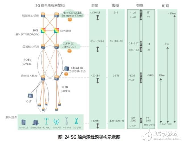
1) 5G wireless & core network function node location and current broadband bearer convergence: 5G New core and FBB CR position is equivalent, MEC/MCE is equivalent to BNG (Broadband Network Gateway), and Cloud BB and OLT are equivalent. .
2) Convergence of cloud architecture features: BNG clouding is in the same cloud as MEC, so the location of CDN can be placed in the location of the core CR of the metropolitan area or sink to BNG. The original CR CDN scheduling function is replaced by DCI, and the CDN content is replaced. Mobile/broadband sharing, content synchronization through the DCI Internet layer, can enhance the business experience of mobile users reaching the video of broadband users.
3) Metropolitan area line coverage convergence: After the OTN equipment sinks to the OLT (Optical Line Terminal), BBU and other integrated services, it is connected to the terminal equipment such as optical fiber direct drive and SDH/CPE/OTN. In the last 1-2 kilometers, it provides large customer dedicated line services, supports fast service opening, end-to-end SDH/OTN hard pipe business, and builds ultra-low latency boutique metro line network. The BNG is still deployed in the core equipment room of the area, and is gradually deployed in the virtual cloud. The OLT is usually deployed in the integrated access equipment room, and the miniaturized OLT is deployed in the user community.
4) Two mainstream network convergence trends in the industry. The aggregation layer is all integrated bearer: one architecture is integrated (OLT/Cloud BB) and above, and the independent bearer is accessed; the other architecture is backbone and metro end-to-end. Integrated bearing.
4 Key technology evolution of optical transport network in the 5G era
5G has created a new era in the field of communications, and has also brought new opportunities to the OTN bearer network. Although the 5G bearer network is divided into three different architectures: pre-transmission, intermediate transmission and back-transmission according to different network bearer functions. But no matter what kind of architecture, compared to the 4G era, the network's demand for ultra-large bandwidth, ultra-low latency and ultra-high flexible scheduling are great technical challenges. Therefore, the optical transmission network realizes the leap of transmission technology performance through continuous technological innovation to adapt to the 5G network bearer demand.
4.1 Low cost and large bandwidth transmission technology
The biggest challenge of the 5G bearer network is the massive bandwidth growth, and the increase of bandwidth will inevitably bring about the increase of cost. Therefore, the key of 5G bandwidth transmission technology is to reduce the transmission cost and power consumption per bit and kilometer. According to different transmission distances, 5G low-cost and large-bandwidth transmission technologies are divided into short-distance non-coherent technology and medium-long-distance low-cost coherent technology.
4.1.1 Short-range incoherent technology
For scenarios with short transmission distances (such as 5G pre-transmission and fiber transmission distance less than 20km), overclocking non-coherent technology based on low-cost optical devices and DSP algorithms has become an important trend.
This type of technology uses DSP algorithms such as spectrum multiplexing, multi-level overlay, and bandwidth compensation to achieve multiple (2x, 4x, or higher) transmission bandwidth growth with lower baud rate optoelectronic devices, such as: DMT (Discrete) Multi-Tone, discrete multi-tone modulation technology, PAM4 (Pulse Amplitude Modulation) technology.
4.1.2 Medium and long distance low cost coherent technology
For longer transmission distances and higher transmission rates, such as 50/60 km or even hundreds of kilometers of core network DCI interconnection and 200 G/400 G or more bandwidth, coherent technology is necessary, the key is how to achieve low Cost related.
The low-cost coherent pluggable color light module based on silicon light technology is currently a technical development direction, including the following features:
(1) Low cost: Using silicon light technology, using a mature and efficient CMOS platform to achieve large-scale integration of optical devices, reducing processes and processes, increasing production capacity, and reducing the overall cost of the original discrete coherent devices.
(2) Coherent communication: Coherent communication can realize long-distance communication, high spectral efficiency, and support for multiple speed adjustments, such as single-wave 100G, 200G, and 400G.
(3) Pluggable module: The silicon optical module uses a single material to realize the multi-function unit of the optical device (except the light source), eliminating the power loss caused by the lattice defects of different materials; the silicon light has higher refractive index, and the device itself is more traditional than Small devices, combined with photonic integration, silicon optical modules can be an order of magnitude smaller than traditional discrete devices; common packaging methods are CFP (Centum Form-factor Pluggable), CFP2, CFP4, QSFP (Quad Small Form-factor) Pluggable, four-channel miniaturized package pluggable).
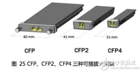
(4) DCO and ACO modules: DCO encapsulates optical components and DSP chips in a module, and outputs them as digital signals. It has good transmission performance, strong anti-interference ability, high integration, low overall power consumption, and easy management and maintenance. The difficulty of the feature is that higher power consumption limits the size of the package. The DSP chip of the ACO module is placed outside the module to simulate the signal output. The optical module consumes less power and can achieve a smaller package, but the analog signal interconnection will bring performance degradation.
4.2 Low latency transmission and switching technology
The ultra-low latency 5G service imposes stringent requirements on the bearer network. Undoubtedly, ROADM-based optical layer hops are the best choice for ultra-low latency, but only for large-scale transmission and exchange at the wavelength level. For small and medium granularity below the wavelength level, such as 1G/2.5G/10G/25G, the delay is mainly reduced by optimizing OTN mapping and packaging efficiency.
4.2.1 ROADM All-optical Network Scheduling Technology
Through the optical layer ROADM device, the optical layer direct communication between the network nodes is realized, thereby eliminating the unnecessary optical-electric-optical conversion in the middle, which can greatly reduce the delay.
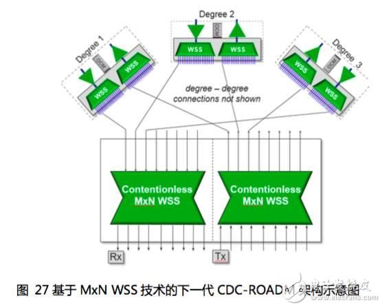
In terms of technology implementation, ROADM based on WSS (Wavelength Selective Switching) technology has become the industry. As shown in the following figure, this is a typical CDC-ROADM (Colorless, Directionless & Contentionless ROADM, wavelength independent, direction independent, unimpeded The technical implementation of RODAM), based on 1xN WSS and MCS (Multi-cast Switching) devices, supports up to 20 channels of up and down waves in up to 20 dimensions through various WSS, coupler, and splitter components.
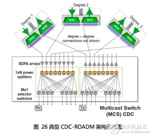
With the continuous evolution of ROADM technology, the next-generation ROADM will move toward higher dimensions and simplify operation and maintenance. WSS based on MCS technology needs to use optical amplifier arrays for compensation because of the large split ratio, and its future evolution is limited. Especially difficult to develop to a higher dimension. MxN WSS technology is an important development direction.
4.2.2 Ultra-low latency OTN transmission technology
Currently, the single-point delay of a commercial OTN device is generally between 10 us and 20 us. The main reason is to cover a variety of service scenarios (such as carrying multiple services and multiple granularities), and adding many unnecessary mapping and packaging steps. This has caused a significant increase in delay.
As the delay requirements become higher and higher, in the future, in certain extremely time-critical scenarios, optimized for specific scenarios, the single-node delay of the ultra-low latency OTN equipment can reach the order of 1 us. Specifically, the existing products can be optimized by the following three ideas: (1) optimizing the package time slot for a specific scenario; (2) simplifying the mapping and encapsulation route; and (3) simplifying the ODU mapping multiplexing path.
4.3 Highly intelligent end-to-end flexible scheduling technology
In the 5G era, the ability to flexibly deploy network resources to cope with bursty traffic is a key feature requirement of 5G networks. For the flexible bandwidth characteristics of the network, the matching between the logical pipe capacity of the bearer hardware system and the size of the transport service is divided into two cases:
(1) The logical pipeline is larger than the granularity of the transmission service, and the single logical pipeline carries the multi-granularity service, and the transmission bandwidth is flexibly configured and adjusted through the ODUflex technology to improve the transmission efficiency.
(2) If the logical pipeline is smaller than the granularity of the transport service, multi-port binding and bandwidth allocation, such as FlexO technology, need to be considered.
In addition, for network end-to-end management and control, efficient network deployment and flexible resource dynamic allocation, and rapid service delivery, need to use a new centralized intelligent management technology such as software defined network (SDN) to achieve.
4.3.1 ODUflex flexible bandwidth adjustment technology
The traditional ODUk is packaged according to a certain standard capacity, which is limited by the capacity standard. It is prone to some smaller granular services that have to be packaged with a larger standard pipeline capacity, resulting in wasted network resources.
ODUflex, the flexible rate ODU, can flexibly adjust the channel bandwidth. The adjustment range is 1.25G~100G. Its features are as follows:
(1) Efficient carrying. The flexible and variable rate adaptation mechanism is provided, and the user can flexibly configure the container capacity according to the size of the service, ensure efficient use of bandwidth, and reduce the transmission cost per bit.

(2) Strong compatibility. Adapt to various service types such as video, storage, and data, and be compatible with the transmission needs of future IP services.
The mapping path in the following figure is: FC4G->ODUflex->ODU2; where ODUflex is mapped to 4 time slots in ODU2, and the remaining time slots can be used to carry other services, and the bandwidth utilization can reach 100%.

For 5G bearers, ODUflex is an effective bearer for 5G network slicing. Different ODUflexs are used to isolate different 5G slicing networks on the bearer network.
4.3.2 FlexO Flexible Interconnect Interface Technology
The advancement of optical layer FlexGrid technology and the development of customer service flexibility adaptation have spawned the OTN layer to further flexibly adapt to the development of optical layer and service adaptation layer. The industry has proposed FlexO technology. Flexible line interfaces are limited by the actual optical module rate, while inter-domain short-range interface applications require low-cost solutions, and FlexO comes into being.
The FlexO interface can reuse the Ethernet gray-light module that supports the OTU4 to implement the N*100G short-distance interconnection interface, so that different equipment vendors can interconnect through the interface. FlexO provides a flexible OTN short-range interconnect interface called FlexO Group for carrying OTUCn, which is implemented by binding the N*100G FlexO interface, where each 100G FlexO interface rate is equivalent to the standard rate of OTU4.
FlexO is mainly used in the following two application scenarios.
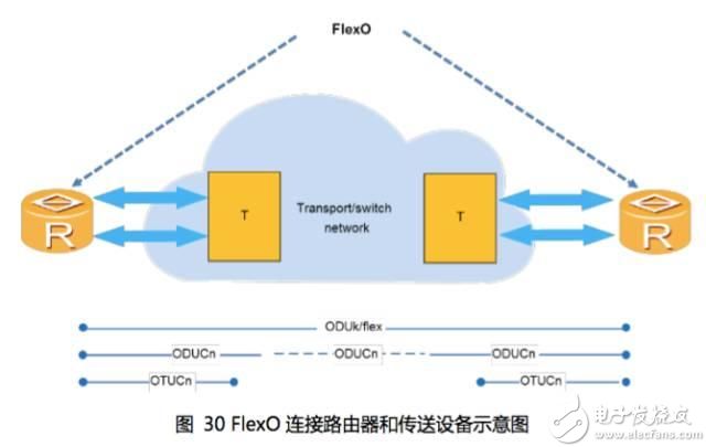
The first scenario is used between the router and the transmitting device. As shown in the above figure, the router encapsulates the data traffic into the ODUk/ODUflex, and then multiplexes it into the ODUCn/OTUCn to complete the multiplex section and link monitoring, and finally carries the OTUCn through the N*100G FlexO interface. The signal completes the interconnection between the router and the transmitting device.
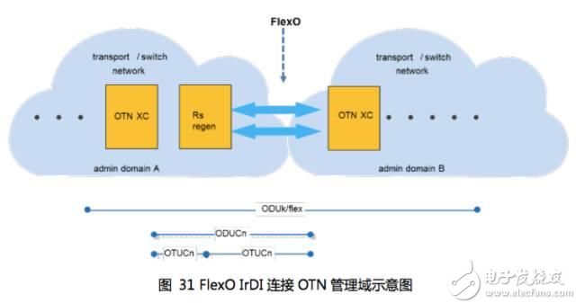
Scenario 2 is used as an inter-domain interface for interworking between different management domains. As shown in the above figure, the OTN signal of the inter-domain interface is OTUCn, which is implemented by carrying the OTUCn signal through the N*100G FlexO interface.
4.3.3 Transmission SDN Fast Service On-demand Delivery Technology
In 2012, the industry first proposed the Transport SDN (TSDN) solution, which is the application and extension of SDN technology in the transport network.
The most important and valuable use case is BoD (Bandwith on Demand): the client subscribes to the bandwidth service through the terminal/Portal, the TSDN controller controls the information of the entire network device, and automatically allocates resources in the background. To achieve rapid distribution of business. The service can better meet the demands of dynamic on-demand and large bandwidth proposed by cloud data center interconnection and enterprise cloud private line, and improve network resource utilization and customer bandwidth experience. In addition, TSDN can also cooperate with OTN delay measurement technology to realize network-wide delay information visualization, and to search, plan, manage, and protect the shortest delay path.
Future 5G networks will pose more challenging demands for TSDN solutions. The transport network must not only have the ability to dynamically and dynamically segment the network to meet the bandwidth, reliability and low-latency bearer requirements of different services, but also need to cooperate with the upper-layer IP and wireless networks to achieve cross-domain cross-layering. Bandwidth and resource coordination ensure end-to-end business service quality requirements. In addition to the collaborative slicing algorithm, the northbound slicing API of the transport network will be the key link to support end-to-end slicing. OIF/ONF is also developing the VTNS (Virtual Transport Network Service) service specification and related northbound API model to meet the challenges of new business in the future.
A manual pulse generator (MPG) is a device normally associated with computer numerically controlled machinery or other devices involved in positioning. It usually consists of a rotating knob that generates electrical pulses that are sent to an equipment controller. The controller will then move the piece of equipment a predetermined distance for each pulse.
The CNC handheld controller MPG Pendant with x1, x10, x100 selectable. It is equipped with our popular machined MPG unit, 4,5,6 axis and scale selector, emergency stop and reset button.
Manual Pulse Generator,Handwheel MPG CNC,Electric Pulse Generator,Signal Pulse Generator
Jilin Lander Intelligent Technology Co., Ltd , https://www.jilinlandermotor.com