PLC basic knowledge
Programmable logic controller that uses a type of programmable memory for its internal program to perform user-oriented instructions such as logic operations, sequence control, timing, counting, and arithmetic operations, and through digital or analog input/output Control various types of machinery or production processes.
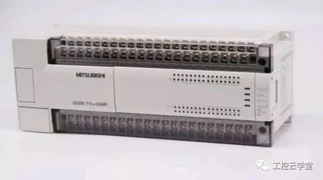
PLC programming controller
The hardware of the PLC is mainly composed of a central processing unit (CPU), a memory, an input unit, an output unit, a communication interface, an expansion interface power supply, a programmer, and software. The CPU is the core of the PLC, and the input unit and the output unit are interface circuits connecting the field input/output device and the CPU, and the communication interface is used for connecting with peripherals such as a programmer and a host computer.
For monolithic PLCs, all components are housed in the same enclosure; for modular PLCs, the components are individually packaged into modules, each module being connected via a bus and mounted on a rack or rail. No matter which type of structure the PLC is, it can be configured and combined according to user needs.
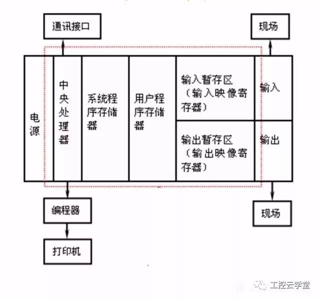
PLCJ basic composition chart
First, the power supply
The power of the programmable logic controller plays an important role in the overall system. If a good, reliable power system does not work properly, manufacturers of programmable logic controllers also place great emphasis on the design and manufacture of power supplies. Generally, the AC voltage fluctuation is within +10% (+15%), and the PLC can be directly connected to the AC grid without taking other measures.
Second, the central processing unit (CPU) - the core of the PLC
The central processing unit (CPU) is the control center of the programmable logic controller. It receives and stores user programs and data typed from the programmer in accordance with the functions assigned by the programmable logic controller system program; checks the status of power, memory, I/O, and watchdog timers, and can diagnose syntax errors in the user program. When the programmable logic controller is put into operation, it firstly receives the status and data of each input device in the field by scanning, and stores them in the I/O image area respectively, and then reads the user program one by one from the user program memory. After the command is interpreted, the result of the logic or arithmetic operation is executed in the I/O image area or data register as specified by the instruction. After all the user programs have been executed, the output status of the I/O image area or the data in the output register is finally transferred to the corresponding output device, and the operation is cycled until the operation is stopped.
In order to further improve the reliability of the programmable logic controller, a large-scale programmable logic controller is also configured with a dual CPU to form a redundant system, or a three-CPU voting system. This way, even if a CPU fails, the entire system will still operate normally.
Third, the memory
The memory that holds the system software is called the system program memory.
The memory that holds the application software is called the user program memory.
Fourth, the input and output interface circuit
1. The field input interface circuit consists of an optical coupling circuit and an input interface circuit of the microcomputer, which functions as an input channel of the interface between the programmable logic controller and the field control.
2. The field output interface circuit is integrated by the output data register, the strobe circuit and the interrupt request circuit, and the programmable logic controller outputs corresponding control signals to the execution components of the field through the field output interface circuit.
Five, programmer and software
Realize the writing, running and debugging of user control programs.
Sixth, the function module
Such as counting, positioning and other functional modules.
Seven, communication module
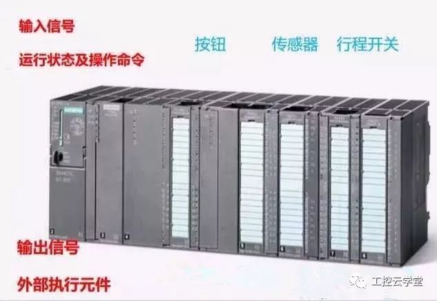
PLC composition
I. Scanning technology
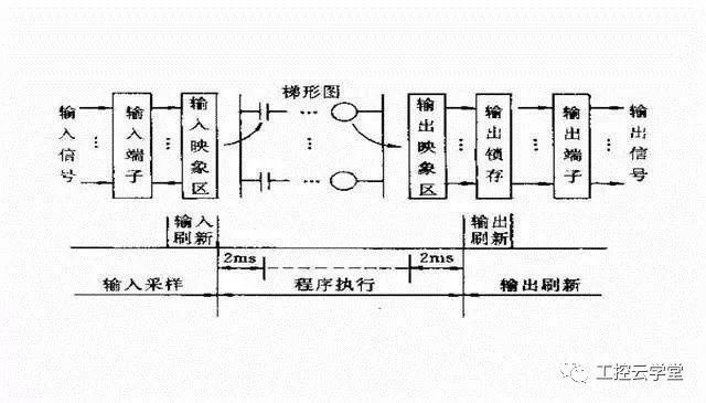
When the PLC is put into operation, its working process is generally divided into three stages, namely, input sampling, user program execution and output refresh. Completing the above three phases is called a scan cycle. During the entire operation, the CPU of the PLC repeatedly executes the above three stages at a certain scanning speed.
(1) Input sampling stage
During the input sampling phase, the PLC reads all input states and data in a scan mode and stores them in the corresponding cells in the I/O map area. After the input sampling is finished, it is transferred to the user program execution and output refresh phase. In these two phases, the status and data of the corresponding unit in the I/O map area does not change even if the input status and data change. Therefore, if the input is a pulse signal, the width of the pulse signal must be greater than one scan period to ensure that the input can be read in any case.
(ii) User program execution phase
During the user program execution phase, the PLC always scans the user program (ladder) in order from top to bottom. When scanning each ladder diagram, the control lines formed by the contacts on the left side of the ladder diagram are always scanned first, and the control lines composed of the contacts are logically operated in the order of first left, then right, first up and then down. And then refreshing the state of the corresponding bit of the logic coil in the system RAM storage area according to the result of the logic operation; or refreshing the state of the corresponding bit of the output coil in the I/O map area; or determining whether to execute the ladder diagram The specified special function instructions.
That is, during the execution of the user program, only the state and data of the input point in the I/O map area will not change, while other output points and soft devices are in the I/O map area or the system RAM storage area. The status and data are subject to change, and the ladder diagrams listed above, the program execution results will work on the ladder diagrams that use these coils or data; instead, the ladder diagrams below, The state or data of the refreshed logic coil can only be applied to the program that is listed above in the next scan cycle.
(3) Output refresh phase
When the scanning user program ends, the PLC enters the output refresh phase. During this time, the CPU refreshes all the output latch circuits according to the corresponding state and data in the I/O map area, and drives the corresponding peripherals through the output circuit. At this time, it is the real output of the PLC.
The same several ladder diagrams are arranged in different order and the results are different. In addition, the results of the operation of the scanning user program are different from the results of the parallel operation of the hard logic of the relay control device. Of course, if the time taken by the scan cycle is negligible for the entire run, there is no difference between the two.
PLC working principle
PLC programming language
Statement table (STL)
LD I0.0
OR Q0.0
AND NOT I0.1
OUT Q0.0
Function block diagram (FBD)
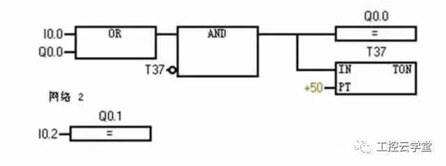
Function block diagram
Ladder diagram (LAD)
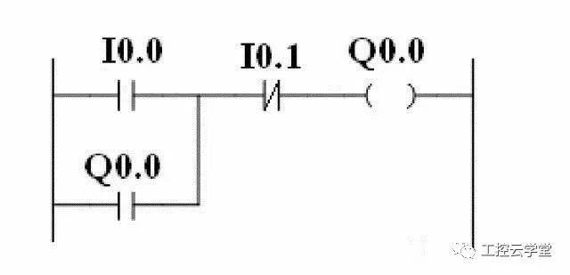
Ladder diagram
The difference between PLC and relay contactor control
1. The components are different
The relay control circuit is made up of many real hardware relays. The PLC is composed of many "soft relays". These "relays" are actually triggers in the memory and can be set to "0" or "1".
2. The number of contacts is different
Hard relays have a limited number of contacts, typically only 4 to 8 pairs; and "soft relays" have an infinite number of contacts that can be programmed because the trigger state can be used any number of times.
3. Different control methods
Relay control is realized by hard wiring between components, so its control function is fixed in the line, so the function is specific and inflexible; and PLC control is solved by software programming, as long as the program changes, the function can be With the change, the control is very flexible. Because the PLC works through the cyclic scan, there is no interlocking and interlocking circuit in the relay control circuit, and the control design is greatly simplified.
4. Different ways of working
In the relay control circuit, when the power is turned on, each relay in the line is in a restricted state, and the combination is closed. In the ladder diagram of the PLC, each "soft relay" is in the cyclic cycle scan on. From the objective point of view, each "soft relay" is subject to the condition, and the on-time is short. That is to say, the working mode of the relay in the control is parallel, and the working mode of the PLC is serial.
lithium ion battery, 5kwh 7Kwh 10Kwh 12Kwh 15KWh 18Kwh Home Power Storage batteries. RV Battery, solar energy storage system
Power Storage Brick
ShenZhen UFO Power Technology Co., Ltd. , https://www.ufobattery.com