Recently, the Digilent open source community has received two questions about how to implement the SPI interface on Zynq SoC and Zynq UltraScale + MPSoC. After answering these questions, I think it is necessary to write an article on how to implement SPI and share it here.
When we use Zynq SoC or Zynq UltraScale + MPSoC in our design, there are two ways to implement the SPI interface:
1. Use the SPI controller on the PS side (there are two SPI controllers on the PS side)
2. Use the AXI Quad SPI (QSPI) IP module configured for standard SPI communication on the PL side
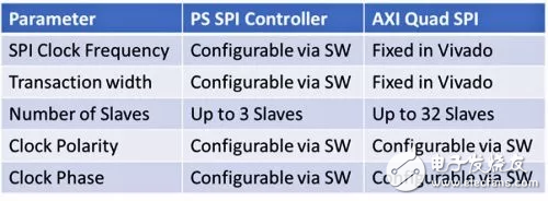
We can choose which method to implement the SPI controller according to the requirements of the application. Both SPI implementations support four SPI modes and can be used as either SPI master or SPI slave. The table below lists some of the differences between them:
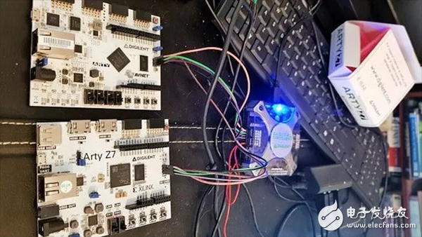
First, we demonstrate how to use the SPI controller on the PS side for SPI transmission. The SPI controller is selected in the Zynq MIO configuraTIon tab, which includes the SPI in the design. In this example, I will connect the SPI signal to the SPI interface of the Digilent ARTY Z7 development board, which requires the use of EMIO via PL I/O.
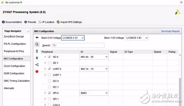
Figure: Enabling SPI and mapping ports to EMIO
After selecting the appropriate option, the only thing to do is to connect the I/O to the SPI port. How to connect depends on whether we need to configure an SPI master or slave. On the SPI controller, each SPI port has a corresponding available input (xxx_i) output port (xxx_o). The correct connection of the port is critical. If the connection is wrong, when you run the application, you will get a completely wrong result, which may take us a few hours to find the source of the problem. In addition, when configured as an SPI slave, there is an input called Slave Select; when used as an SPI master, there are three select pins.
When the I/O is properly configured and the project is created, we can configure the SPI controller as a master or slave using the SPI configuration option in the application. To configure and transfer data using the PS SPI controller, you need to use the API interface provided by the BSP (Board Support Package) defined by XSPIps.H. In the first example, we configured the SPI controller as an SPI master.
By default, SPI uses 8-bit transfers. However, we can also configure the transmission to be larger 16 or 32 bits. For 8-bit transfers, we can use the u8 data type in C programs. For 16-bit or 32-bit transfers, 16 or 32 bits are used to read and write the data.
In the beginning, this can cause some problems or generate compiler warnings, because the two data transfer API functions shown below need to send and receive buffers of data type u8:
S32 XSpiPs_Transfer(XSpiPs *InstancePtr, u8 *SendBufPtr, u8 *RecvBufPtr, u32 ByteCount);
S32 XSpiPs_PolledTransfer(XSpiPs *InstancePtr, u8 *SendBufPtr, u8 *RecvBufPtr, u32 ByteCount);
To solve the problem of using u16 and u32 data types, we need to convert the buffer to a u8 pointer as follows:
XSpiPs_PolledTransfer(&SpiInstance, (u8*)&TxBuffer, (u8*)&RxBuffer, 8);
This setup will allow us to transfer data that is 8, 16, or 32 bits in size. To demonstrate this setup, I connected the SPI master IO to the Digilent Digital Discovery pocket instrument to test the transmitted data. Use the above method to change the data width from 8 bits to 16 bits in the application software.
Figure: Arty Z7 development board with Digital Discovery pocket instrument
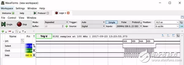
Figure: Zynq SoC PS SPI master sends four 8-bit words
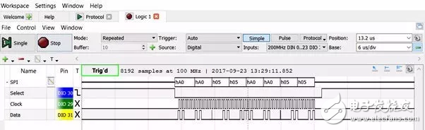
Figure: PS SPI master sends four 16-bit words
Another way to implement the SPI interface is to use the AXI QSPI IP core. This method requires a lot of setup in Vivado and takes a long time. In the AXI QSPI configuration dialog, we can configure the width, frequency, and number of slaves. The most important option is to choose whether the AXI QSPI IP core acts as an SPI master or slave. If you want to configure as an SPI master, you must check the enable master mode option. If you are configuring as a slave, you must deselect this option to ensure the presence of the SPISel input pin. When the SPI IP core acts as a slave, this pin needs to be connected to the slave select. port of the master.
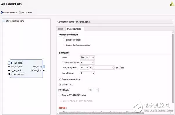
Figure: Configuring the AXI Quad SPI
210W Medical Power Supply,210W Medical Device Power Supply,210W Medical Power Adapter,210W Rade Power Supplies
Shenzhen Longxc Power Supply Co., Ltd , https://www.longxcpower.com